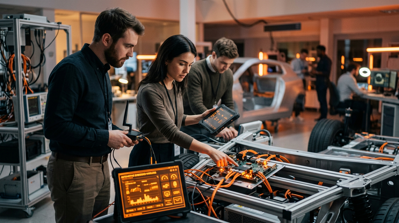
A UWB test bench is the piece of infrastructure that decides whether your ranging programme is measurable or merely hopeful. Every other part of a vehicle access or in cabin sensing project produces an opinion. The bench produces evidence.
It is also the part that gets built last, badly, by whoever has time. That is the wrong order, because a bench assembled after the firmware cannot answer the questions the firmware raises. By then you are reading logs, and logs record what your device believed rather than what happened on air.
This article covers the four subsystems a UWB test bench needs, and why each one exists: the phones you cannot control, the anchor rig whose calibration sets your accuracy floor, the vehicle bus that tells you what the car was doing at the moment of failure, and the protocol capture that is the only independent witness. It is the companion piece to our walkthrough of automotive UWB testing from development kit to a validated ECU, which covers the programme; this one covers the bench.
What a UWB test bench has to reproduce
Ranging is a negotiation between two devices, mediated by an out of band channel, constrained by a regulatory duty cycle, and triggered by vehicle state. A bench that reproduces only one of those four will pass tests that a vehicle fails.
| Subsystem | What it contributes | What breaks without it |
|---|---|---|
| Phone fleet as device under test | The half of the link you do not own, across vendors and OS versions | Failures that only appear on a phone model you did not have |
| Anchor rig and ground truth | A known distance to measure against, and a calibrated baseline | Accuracy claims with no reference, and antenna delay bias mistaken for algorithm error |
| Vehicle bus interface | What the car was doing when the radio behaved oddly | Ranging faults that cannot be tied to a trigger, a door state or an ignition transition |
| Protocol capture | An independent record of the over the air exchange | Two devices disagreeing, and two logs that both look correct |
The rest of this article takes each in turn.
Phones are the hardest device under test
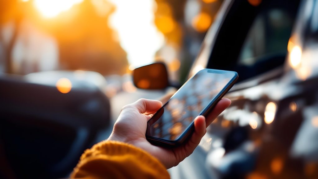
In a digital key programme the vehicle is your product and the phone is somebody else’s. You do not control its silicon, its stack, its OS scheduler or its update cadence, and it is the half of the link your customer actually holds.
Start with what the platforms expose. The Android UWB Jetpack library provides ranging at a stated 10 cm accuracy using more than 500 MHz of bandwidth, with devices taking a controller and initiator role or a controlee and responder role. It requires Android 12 or higher and a device reporting the android.hardware.uwb system feature. Apple’s side is the Nearby Interaction framework, which exposes the UWB chipset in supported iPhones and Apple Watches to third party accessories, and Apple publishes both an accessory protocol specification for accessory manufacturers and a separate UWB interoperability specification for chipset vendors.
Three properties of that arrangement drive bench design.
The first is device diversity. As of January 2025 Android’s supported list included Google Pixel 6 Pro and later Pro models, Pixel Fold and Pixel Tablet, Motorola Edge 50 Ultra, and Samsung Galaxy Note 20, Galaxy S21 Plus and later Plus and Ultra models, and Galaxy Z Fold2 and later. Each of those is a different UWB implementation. A bench with one Android phone and one iPhone tests two implementations out of a dozen your customers own.
The second is session security configuration. Android supports Provisioned STS with a 16 byte key, available from Android 14, which mitigates replay and relay attacks, and Static STS with an 8 byte key, which is susceptible to replay. Those are not equivalent test cases. If your vehicle accepts both, your bench has to exercise both, and your security case has to say which one the product actually requires.
The third catches teams out repeatedly. Android applications must be in the foreground unless the device supports background ranging, and where it is unsupported no ranging reports are produced until the app returns to the foreground. Background support is specifically excluded on Pixel 6 Pro, Pixel 7 Pro, Pixel Fold, and Samsung phones running Android 13 or lower. A passive entry experience that assumes the phone is ranging in a pocket with the screen off is making an assumption the platform does not always honour, and that is an OS behaviour rather than a bug you can fix in your firmware.
The practical consequence is that the phone side of a UWB test bench is a maintained asset, not a drawer of handsets. It needs a defined matrix of models and OS versions, a policy on when to update them, and a record of which build each result was taken on. Reference device availability also gates certification schedules more often than engineering readiness does.
Anchors: geometry, and the calibration that sets your accuracy floor
The anchor side is the part you do own, which makes the errors your responsibility.
The single largest source of systematic bias is antenna delay. Every device adds propagation time through its RF path and antenna structure before the signal reaches air, and two way ranging measures the combined delay of both ends. Get it wrong and every measurement is offset by a constant that no filtering removes.
The numbers make the point. The DW3000 counts time in units of 15.65 picoseconds, which corresponds to roughly 4.7 millimetres of propagation per unit. A typical antenna delay value of 16,530 units gives about 517 nanoseconds of aggregate delay across the pair, with published figures ranging from about 514 nanoseconds in application material to about 573 nanoseconds in the decaRanging reference. Five hundred and seventeen nanoseconds is roughly 155 metres of propagation. A one percent error in that calibration therefore puts something like 0.8 metres of bias into a range you intend to quote to ten centimetres.
Two further details decide how you calibrate. The correct value depends on the PCB layout and the antenna type, and there is batch to batch variation between chips, so it is a per design and arguably per unit measurement rather than a datasheet constant. And with only two devices you can measure the combined delay but must assume it splits evenly between them; with three or more devices the individual delays become solvable. Build the rig with at least three nodes for that reason alone.
| Error source | Symptom | How the bench removes it |
|---|---|---|
| Antenna delay miscalibration | Constant offset across all distances | Multi node calibration at surveyed distances, per hardware revision |
| Cable and connector delay | Offset that changes when the rig is rebuilt | Measure and record the RF path; treat cables as calibrated items |
| Ground truth uncertainty | Accuracy claims you cannot defend | Surveyed positions, a measured baseline, documented uncertainty |
| Antenna placement and orientation | Error that varies with angle rather than distance | Characterise across the intended angular range, not on boresight only |
| Multipath and NLOS | Errors that appear only in the vehicle | Test in the production body, with trim, glass and occupants |
| Clock drift and temperature | Slow drift across a long run | Chamber runs with the RF path in the loop |
The rule that follows is simple. Until a UWB test bench has a ground truth better than the accuracy you are claiming, you are not measuring accuracy, you are measuring disagreement.
CAN coordination: what the car was doing at the moment it failed
This is the subsystem most UWB test bench builds leave out, and its absence produces the most frustrating class of bug report: intermittent, unreproducible, and described in prose.
Vehicle access ranging does not run continuously. It is triggered, and under European rules it has to be. ETSI’s vehicular UWB standard requires trigger before transmit for vehicle transceivers, with cumulated transmission capped at 50 milliseconds in any 10 second window, so the radio is idle until vehicle state says otherwise. That makes the trigger, and everything around it, part of the system under test.
The failures that matter live in the seam. A ranging session that starts before the door handle capacitive sensor settles. An approach detected while the vehicle is transitioning out of sleep and the anchor has not finished initialising. A session torn down because the lock state changed mid exchange. None of these are radio faults, and all of them present as radio faults.
Correlating the two domains means capturing vehicle bus traffic on the same timebase as the radio exchange. needCode’s modular UWB sniffer includes a CAN adapter for exactly this, alongside a BLE companion for out of band session parameter capture, so a single capture shows the vehicle event, the out of band negotiation and the resulting ranging exchange in one timeline.
Once you have that, the debugging conversation changes shape. Instead of “ranging sometimes fails on approach”, you get “the session was configured with a different STS index than the one the vehicle expected, 40 milliseconds after the wake trigger”. The second is a fix. The first is a meeting.
Protocol capture: the only independent witness
UWB is harder to observe than any other wireless stack in a vehicle, which is why so few teams observe it at all, and why capture is the component that most changes what a UWB test bench can tell you.
There is no carrier to lock onto. The preamble requires code correlation rather than simple detection. The payload is protected by a scrambled timestamp sequence, so a capture without key material shows you that something happened without showing what. Generic spectrum tools see energy. They do not see a ranging round.
That matters because interoperability failures are, by definition, disagreements between two implementations. Your firmware log states what your device believed. The phone’s log, if you could read it, would state what it believed. Neither is evidence about the exchange. Only an independent capture is.
| Failure class | What your log shows | What capture shows |
|---|---|---|
| Session parameter mismatch | A session that failed to start, reason code generic | Both sides’ negotiated parameters, and which field diverged |
| STS desynchronisation | Ranging results that stop arriving | The counter values and where they parted company |
| Out of band negotiation fault | A UWB failure | A BLE exchange that agreed the wrong configuration before UWB ever started |
| Timing violation | Nothing, because your device behaved correctly | The other device’s frame arriving outside the expected window |
| Interop failure against a specific phone | An unexplained failure rate on one model | The frame level difference between that model and the ones that work |
The capability worth specifying when you buy or build this is: raw 802.15.4a and 802.15.4z PHY capture across channels 1 to 9, MAC dissection, decoders for the profiles you actually use including FiRa, CCC Digital Key with dynamic STS, Aliro and omlox, static and dynamic STS decryption with key injection, and STS integrity detection even without keys. A PHY scanner with a sweep mode earns its place the first time you meet a device whose configuration you do not know.
Equally important is how the capture leaves the instrument. A Wireshark plug in with named protocol fields makes the data readable by engineers who are not UWB specialists. A REST and Python API makes it scriptable, which is what turns a debugging tool into a test asset.

Wiring the bench into CI
A UWB test bench used by hand finds bugs. The same bench wired into continuous integration prevents them.
The pattern that works is a rack mounted capture instrument permanently connected to a small anchor rig and a phone or two, driven by the same pipeline that builds the firmware, with pass and fail rules applied to the captured exchange rather than to a log line. A ranging regression introduced on a Tuesday is then found on Tuesday night, by a machine, with a capture attached to the failure.
This is the same discipline as automated Bluetooth Profile Tuning Suite regression, and it produces the same effect on the calendar. It also produces something a manual bench never does: a growing archive of captures from known good builds, which is what lets you answer “when did this change” rather than “why is this happening”. Our hardware in the loop and RF test automation work is built around that idea.
A practical build order
Build a UWB test bench in this order, because each stage depends on the one before it being trustworthy.
Start with ground truth and anchor calibration, using at least three nodes so individual antenna delays are solvable rather than assumed. Until the rig can measure a known distance correctly, nothing measured on it means anything.
Add protocol capture second, before you add phones. Capture against your own devices first, so that when a phone joins you already know what a correct exchange looks like.
Add the phone fleet third, with a documented model and OS matrix and a policy on updates. Expect to discover platform behaviours rather than bugs.
Add the vehicle bus interface fourth, and only then start chasing intermittent field reports, because that is the point at which they become tractable.
Wire the whole thing into CI last, once the sequence is stable enough that a failure means something. A flaky bench in CI trains everyone to ignore it.
Where needCode fits
needCode built its own UWB protocol analyser because the instruments did not exist, which means the team writing ranging firmware also owns the tool that proves it. The sniffer does 802.15.4a and 802.15.4z PHY capture across channels 1 to 9 with FiRa, CCC Digital Key, Aliro and omlox decoders, static and dynamic STS decryption with key injection, a BLE companion for out of band session parameters and a CAN adapter for vehicle context. It ships as a desktop USB unit, a battery powered portable, and a 1U rack mount intended for exactly the CI arrangement described above, with a Wireshark plug in and a REST and Python API. That last form factor exists because a UWB test bench belongs in a rack, running unattended, not on a desk being driven by hand.
Around that, the team does chipset bring up on Qorvo QM33 and QM35, NXP Trimension, STMicroelectronics and Infineon parts as well as legacy DW1000 and DW3000 designs, anchor and antenna work, and the ranging and access systems that sit on top. needCode is a certified Qorvo partner of more than eight years, a Nordic Semiconductor Design Partner for EMEA and a UWB Alliance member, and holds ISO/IEC 27001:2022 and ISO 9001:2015.
If you have a UWB programme that is debugging from logs, the fastest improvement available is usually not more engineers. It is an independent view of the air. Our automotive and SDV practice covers digital key, secure ranging and in cabin sensing as one programme, and a bench that serves all three costs little more than one that serves a single function.
To talk through what your bench is missing, book a discovery call.
Frequently asked questions
Because you own neither the hardware nor the software policy, and the behaviour changes underneath you. Android exposes ranging through the UWB Jetpack library at a stated 10 cm accuracy with controller and controlee roles, requiring Android 12 or higher and a device advertising the UWB system feature, while Apple exposes its chipset through Nearby Interaction with a separate accessory protocol specification and an interoperability specification for chipset vendors. Each supported handset is a different implementation, and the supported list already spans several Pixel, Motorola and Samsung families. Platform policy adds a second layer: Android applications must be in the foreground unless the device supports background ranging, and background support is excluded on Pixel 6 Pro, Pixel 7 Pro, Pixel Fold and Samsung phones on Android 13 or lower. A passive entry design that assumes ranging continues with the phone pocketed and the screen off is relying on behaviour the platform does not universally provide.
Enough to invalidate the specification you are claiming. The DW3000 counts time in 15.65 picosecond units, about 4.7 millimetres of propagation each. Aggregate antenna delay across a ranging pair typically lands around 517 nanoseconds, with published figures from roughly 514 to 573 nanoseconds. That 517 nanoseconds is about 155 metres of equivalent propagation, so a one percent calibration error introduces roughly 0.8 metres of systematic bias into a measurement you intend to quote to ten centimetres. It is a constant offset, so no amount of filtering or averaging removes it. The correct value depends on your PCB layout and antenna type and varies batch to batch between chips, which makes it a per design measurement rather than a datasheet lookup. Use three or more nodes during calibration, because with only two you can measure the combined delay but have to assume it splits evenly.
Because vehicle access ranging is triggered by vehicle state rather than running continuously, and the failures cluster in that seam. European rules require trigger before transmit for vehicle transceivers, with cumulated transmission capped at 50 milliseconds in any 10 second window, so the radio is idle until something in the car wakes it. The bugs that follow are things like a session starting before a door handle sensor settles, an anchor that has not finished initialising when an approach is detected, or a session torn down by a lock state change mid exchange. All present as radio faults and none are. Capturing bus traffic on the same timebase as the over the air exchange converts “ranging sometimes fails on approach” into a specific statement about which event preceded which frame, and by how many milliseconds.
Not for the failures that matter. A log records what your device believed happened, and interoperability failures are disagreements between two devices about what happened. Neither party’s log is evidence about the exchange itself. UWB is also harder to observe than other stacks: there is no carrier to lock onto, the preamble needs code correlation, and payloads are protected by a scrambled timestamp sequence, so generic capture tools show energy rather than ranging rounds. An analyser with raw 802.15.4a and 802.15.4z PHY capture, profile decoders, and static and dynamic STS decryption with key injection shows both sides’ negotiated parameters and exactly which field diverged. Adding a companion capture of the out of band session negotiation over BLE resolves the single most common failure class, where two devices agreed on the wrong configuration before UWB ever started.
Ground truth and anchor calibration first, with at least three nodes so individual antenna delays are solvable rather than assumed, because until the rig measures a known distance correctly nothing else it produces means anything. Protocol capture second, exercised against your own devices, so you learn what a correct exchange looks like before a third party device joins. The phone fleet third, with a documented model and operating system matrix and a policy on when handsets get updated. The vehicle bus interface fourth, at which point intermittent field reports become tractable. Continuous integration last, once the sequence is stable enough that a failure carries information, because a flaky bench wired into CI teaches the whole team to ignore it.