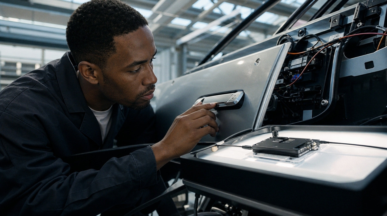
Automotive UWB testing is where most in cabin sensing programmes discover what they actually signed up for. The demo works. A UWB radar development kit sitting on a bench detects a breathing target through a seat back in an afternoon, the ranging numbers look clean, and somebody shows a video to a steering group. Then the same function has to become an ECU that survives 150 degrees, holds a spectrum mask, passes conformance and interoperability certification, and produces evidence for a type approval file.
The distance between those two states is measured in years, not sprints, and almost none of it is algorithm work. It is qualification, regulatory envelope, RF validation on production hardware, and test automation.
This article walks the path stage by stage, with the numbers that set the schedule: AEC-Q100 grades and durations, the ETSI limits that constrain your firmware, what certification actually tests, and what automotive UWB testing looks like when it is done properly rather than manually.
Why UWB is moving into the cabin
Two demand curves are pulling the same radio into vehicles from different directions.
The first is access. The automotive digital key UWB market exists because Bluetooth proximity cannot resist a relay attack and UWB time of flight can. That put UWB anchors in door pillars and cabins across a large part of the premium fleet.
The second is sensing. The automotive occupant sensing system market and the wider automotive in cabin sensing technology market are being driven by Euro NCAP, which since January 2025 awards no child presence detection points for indirect sensing. That forces a sensor that detects respiration rather than inferring occupancy from door logic.
The interesting part for an engineering team, and the reason automotive UWB testing has become its own discipline, is that these two curves land on the same silicon. NXP’s Trimension NCJ29D6A is described as the first automotive device combining ranging and short range UWB radar on a single chip with an integrated MCU, supporting IEEE 802.15.4 HRP and 802.15.4z BPRF and HPRF, and targeting in cabin child presence detection, seat belt reminder and kick sensor alongside secure access, in model year 2025 vehicles.
That convergence is what makes the in cabin occupancy detection radar sensor market worth engineering for rather than buying as a discrete module. One radio, several functions, one qualification effort. It is also what makes the validation harder, because a part serving access and sensing has to be validated for both.
What a UWB radar development kit proves, and what it does not
A development kit is a perfectly good instrument for answering one question: is the physics on my side. It will tell you whether the ranging accuracy is achievable, whether respiration is detectable through your seat geometry, and whether your intended algorithm converges.
It will not tell you anything about the twelve months that follow.
| Dimension | What the development kit gives you | What the validated ECU requires |
|---|---|---|
| Silicon | An evaluation part, often commercial grade | AEC-Q100 Grade 1 or Grade 2, with qualification data you can cite |
| Temperature | Room temperature on a bench | Minus 40 to plus 85 degrees for a vehicle transceiver, verified electrically at the extremes |
| RF environment | Open lab, one radio | Final mechanical position, every co located radio active, body shell reflections |
| Antenna | Kit antenna on a reference layout | Your antenna, your ground plane, your trim material, measured |
| Regulatory | Test mode, unconstrained transmission | Spectrum mask, EIRP limits and mandated mitigation techniques enforced in firmware |
| Protocol | Vendor stack in a known configuration | Certified conformance plus interoperability against other vendors’ silicon |
| Test | Manual runs, judged by eye | Automated regression with pass and fail rules, run per commit |
| Evidence | Screenshots | A traceable file an auditor will read |
The honest framing is that a UWB radar development kit closes the feasibility question and opens the automotive UWB testing programme. Teams that treat the kit result as project completion at eighty percent are usually at about fifteen.
Silicon selection is a decision you make two years early
The single most consequential choice in an automotive UWB testing programme happens before any firmware is written, because automotive qualification data cannot be created retrospectively.
AEC-Q100 defines four temperature grades: Grade 0 covers minus 40 to plus 150 degrees, Grade 1 minus 40 to plus 125, Grade 2 minus 40 to plus 105, and Grade 3 minus 40 to plus 85. Automotive radar ICs typically require Grade 1 or Grade 2 qualification. Parts do exist at these grades: ST’s ST64UWB-A500 is AEC-Q100 Grade 2 qualified, for example.
The qualification itself runs across seven test groups.
| Group | Covers | Representative stress |
|---|---|---|
| A | Environmental stress | HTOL at 150 degrees junction for 1,000 hours; temperature cycling minus 40 to plus 150 for 1,000 cycles; HAST at 130 degrees and 85 percent relative humidity for 96 hours |
| B | Accelerated lifetime | Electromigration, time dependent dielectric breakdown |
| C | Package assembly integrity | Wire bond pull, ball shear, solderability |
| D | Die fabrication reliability | Gate oxide integrity, hot carrier injection |
| E | Electrical verification | Parametric performance at temperature extremes |
| F | Defect screening | Burn in |
| G | Cavity package integrity | Package specific |
Two numbers decide your programme plan. The qualification sample runs from 77 to 231 devices depending on the test, and the acceptance criterion allows zero failures, with any failure requiring root cause analysis and corrective action before the qualification can continue. A full AEC-Q100 programme takes six to twelve months, and the HTOL stress alone is 42 days of elapsed time for the 1,000 hour soak before you add setup and measurement.
If you are selecting an already qualified part, this is somebody else’s calendar and you inherit the data. If your programme is driving a new part, or a variant, this sits on your critical path and no amount of engineering effort compresses a 1,000 hour soak.

The regulatory envelope shapes your firmware, not just your paperwork
This is the stage of automotive UWB testing that surprises software teams, because the constraints arrive as timing rules that have to be implemented in the radio scheduler.
ETSI EN 302 065-3-1 governs UWB devices installed in road and rail vehicles in Europe. Two bands are permitted for vehicular access systems: 3.8 to 4.2 GHz and 6.0 to 8.5 GHz. The maximum mean EIRP spectral density is minus 41.3 dBm per MHz in both, with a peak EIRP limit of 0 dBm defined in 50 MHz.
The part that lands in firmware is the mitigation requirement. Type 1 equipment, meaning vehicle transceivers, must operate on a Trigger Before Transmit basis: the device transmits only in response to a trigger, with a maximum timeout of 10 seconds after the trigger event, and cumulated transmission time capped at 50 milliseconds within any 10 second window.
Read that as a design constraint rather than a compliance checkbox. Fifty milliseconds of transmission in ten seconds is a hard budget that your ranging schedule, your radar frame rate and your sensing duty cycle all have to share. A child presence detection algorithm that wants continuous observation and a digital key that wants responsive approach detection are competing for the same 0.5 percent duty allowance. Architect that early, because discovering it during conformance testing means rewriting the scheduler.
The 3.8 to 4.2 GHz band adds Low Duty Cycle limits on top: maximum on time of 5 milliseconds, total off time greater than 950 milliseconds per second, and total on time under 18 seconds per hour. The standard also sets environmental testing across minus 40 to plus 85 degrees for vehicle transceivers, which is the temperature range your RF performance has to hold across, not just survive.
Our own longer treatment of UWB spectrum allocation and regulation covers how these limits differ across regions, which matters if the same ECU ships globally.
What automotive UWB testing actually involves
Here is where the work concentrates, and where the difference between a supplier who has done this and one who has not becomes visible within a single conversation.
| Test activity | What it catches | Where it has to happen |
|---|---|---|
| RF conformance to the spectrum mask | EIRP and duty cycle violations that block certification | Accredited lab, but pre tested in house or you will fail expensively |
| Ranging accuracy characterisation | Antenna delay calibration errors, cable delay, clock offsets | Controlled RF environment, on production hardware |
| In cabin sensing validation | Detection failures through seat backs, blankets, footwells, and false positives | Production body, not a mule and not a bench |
| Protocol capture and dissection | Session parameter mismatches, STS desynchronisation, timing faults invisible to logs | Live over the air capture with a UWB sniffer |
| Coexistence with BLE, Wi-Fi and cellular | Arbitration failures and desense that appear only under simultaneous load | Final mechanical position, all radios loaded |
| Environmental and thermal | Drift in ranging accuracy across temperature | Chamber, with the RF path in the loop |
| Interoperability | Failures against other vendors’ silicon that your own reference stack never reveals | Certification lab and plugfests |
| Regression automation | Everything above, silently reintroduced by a later commit | CI, per commit, on production hardware |
Two of these deserve expanding.
Protocol capture is the one most teams lack and most need. UWB debugging is unlike other wireless stacks because there is no carrier to lock onto, the preamble requires code correlation, and the payload is encrypted with a scrambled timestamp sequence. Firmware logs tell you what your own device believed happened, which is exactly the wrong evidence when two implementations disagree. needCode’s modular UWB sniffer does raw 802.15.4a and 802.15.4z PHY capture across channels 1 to 9, with decoders for FiRa, CCC Digital Key including dynamic STS, Aliro and omlox, static and dynamic STS decryption with key injection, a BLE companion for out of band session parameter capture, and a CAN adapter for vehicle context. It exposes a Wireshark plug in with named fields plus a REST and Python API, which is what turns capture from a debugging activity into a test asset.
Regression automation is the second. The pattern that works is a rack mounted capture instrument wired into CI with pass and fail rules, so a ranging regression introduced on a Tuesday is caught on Tuesday night rather than at a plugfest. That is the same discipline as the hardware in the loop and RF test automation applied to Bluetooth qualification, and it has the same effect on the calendar: certification becomes a scheduled event rather than a fire drill.
Certification and interoperability
Conformance and interoperability are separate questions, and automotive UWB testing has to answer both.
The FiRa certification programme runs both parts. Conformance validates protocol compliance across the physical, MAC and link layers. Interoperability confirms the device works with other vendors’ chipsets. Testing runs through FiRa Authorized Test Laboratories using FiRa Validated Test Tools, and the programme now includes conformance certification for CCC Digital Key UWB and for Aliro, so an access programme can address FiRa and CCC through a converging route rather than two disconnected ones.
That convergence is deliberate. In November 2023 the CCC and FiRa formed the Joint UWB MAC PHY Working Group to jointly develop and maintain the UWB specifications used in the Digital Key, with the stated aim of long term interoperability as the underlying IEEE 802.15.4 standards evolve.
The practical consequence for planning is that interoperability failures are the ones that arrive late and cost most. A device tested only against your own reference stack will pass everything you run and then fail against a phone from a vendor you did not model. Book plugfest attendance and reference device access early, because availability, not engineering readiness, is often what gates the date.
Productization: the distance between a demo and a build
The final stage is the one nobody puts in the Gantt chart at kickoff, and it runs alongside the last of the automotive UWB testing rather than after it.
Design for manufacturing hardens the design for volume: component selection, assembly, and test access decided before the line finds the problem for you. Manufacturing test means a strategy and fixtures that verify every unit rather than a sample, which for a UWB product means an RF measurement in the production flow, not just a functional check. Certification coordination means treating FiRa, CCC and Bluetooth SIG submissions as scheduled items inside the production timeline rather than a hurdle discovered at the end. And supply chain work keeps the ramp from stalling between pilot and volume.
needCode calls this productization, and describes it as the unglamorous distance between a demo that works and a product you can build at volume. That is a fair description of where UWB programmes lose their schedule.
Where needCode fits
needCode takes UWB programmes from feasibility through to a validated, certified ECU: chipset bring up on Qorvo QM33 and QM35, NXP Trimension, STMicroelectronics and Infineon parts as well as legacy DW1000 and DW3000 designs, ranging and radar firmware, antenna and placement work, and the automotive UWB testing infrastructure underneath it. The team is a certified Qorvo partner of more than eight years, a Nordic Semiconductor Design Partner for EMEA and a UWB Alliance member, and holds ISO/IEC 27001:2022 and ISO 9001:2015.
The differentiator worth naming is the sniffer. needCode built its own UWB protocol analyser because the debugging tools did not exist, which means the same team that writes your ranging stack also owns the instrument that proves it. For in cabin child presence detection and digital key programmes alike, that shortens the loop between a field failure and a root cause considerably.
Most vehicle programmes start with a scoped feasibility study on your own cabin geometry and silicon shortlist, which is the right size of commitment before the qualification calendar starts. Our automotive and SDV practice covers digital key, secure ranging, in cabin sensing and OTA as one programme, which matters when one radio has to serve all of them inside a single duty cycle budget.
If you have a development kit result and need to know what the next eighteen months look like, book a discovery call.
Frequently asked questions
Plan in years rather than quarters, and expect the calendar to be set by qualification and automotive UWB testing rather than by engineering. If you are using an already AEC-Q100 qualified part, you inherit that data and your critical path becomes RF validation on production hardware, certification, and the vehicle programme’s own gates. If your programme drives a new part or variant, AEC-Q100 alone runs six to twelve months, with the high temperature operating life stress taking 42 days of elapsed time for the 1,000 hour soak before setup and measurement. Layer on antenna and placement validation on production bodies, conformance and interoperability certification through an accredited lab, and coexistence testing with every co located radio active. The development kit answers feasibility. It does not shorten any of the above.
Automotive radar ICs typically need Grade 1 qualification, covering minus 40 to plus 125 degrees, or Grade 2 covering minus 40 to plus 105. Qualification runs across seven test groups: environmental stress including high temperature operating life at 150 degrees junction temperature for 1,000 hours, temperature cycling from minus 40 to plus 150 for 1,000 cycles and highly accelerated stress at 130 degrees and 85 percent humidity for 96 hours; accelerated lifetime simulation; package assembly integrity; die fabrication reliability; electrical verification at temperature extremes; defect screening including burn in; and cavity package integrity. Sample sizes run from 77 to 231 devices depending on the test, and the acceptance criterion is zero failures, with any failure triggering root cause analysis and corrective action before the programme continues.
ETSI EN 302 065-3-1 covers UWB devices installed in road and rail vehicles. Vehicular access systems may use 3.8 to 4.2 GHz and 6.0 to 8.5 GHz, with a maximum mean EIRP spectral density of minus 41.3 dBm per MHz and a peak EIRP limit of 0 dBm defined in 50 MHz. The requirement that most affects firmware is Trigger Before Transmit for vehicle transceivers: transmission only in response to a trigger, a maximum timeout of 10 seconds after the trigger, and cumulated transmission time of no more than 50 milliseconds in any 10 second window. The lower band adds Low Duty Cycle limits of 5 milliseconds maximum on time, more than 950 milliseconds total off time per second, and under 18 seconds total on time per hour. Environmental testing spans minus 40 to plus 85 degrees for vehicle transceivers.
Because logs record what your device believed, and interoperability failures are disagreements between two devices. UWB is harder to observe than other wireless stacks: there is no carrier to lock onto, the preamble needs code correlation, and payloads are encrypted with a scrambled timestamp sequence, so generic capture tools do not work. A purpose built analyser gives raw 802.15.4a and 802.15.4z PHY capture across channels, protocol decoders for FiRa, CCC Digital Key with dynamic STS, Aliro and omlox, and static and dynamic STS decryption with key injection. Adding a companion capture of the out of band session parameters over BLE is what resolves the most common class of failure, where two devices negotiated different session configurations and neither log shows it. Wired into CI with pass and fail rules, the same instrument turns ranging regressions into an overnight finding.
They are converging. The FiRa certification programme covers conformance across the physical, MAC and link layers plus interoperability against other vendors’ chipsets, run through FiRa Authorized Test Laboratories using FiRa Validated Test Tools. FiRa has added conformance certification for CCC Digital Key UWB and for Aliro to that programme, so an access system can be addressed through one route rather than two disconnected ones. Underneath, the CCC and FiRa formed a Joint UWB MAC PHY Working Group in November 2023 to jointly develop and maintain the UWB specifications used in the Digital Key, so the two bodies now maintain the radio layer together as IEEE 802.15.4 evolves. Plan for both conformance and interoperability, and secure reference device access early, since availability often gates the schedule more than engineering readiness does.