Facts checked on 16 October 2026
Short answer
Every UWB device built on Qorvo silicon carries small unit-specific errors: the antenna delay, the crystal frequency offset, the transmit power and, in angle-of-arrival designs, the PDoA offset. Qorvo’s DW3000 datasheet quotes ranging accuracy of about ±6 cm after calibration and roughly ±15 cm without it.
Production calibration measures these values at the end of the line in a fixed order (crystal, transmit power, antenna delay, PDoA), stores them in OTP or flash and verifies them before shipping. Plan it with the hardware, not after the first field complaints.
Why calibration matters: centimetres from picoseconds
UWB ranging measures time. Qorvo’s drivers count time in device units of 1/(128 × 499.2 MHz), about 15.65 ps, and radio waves travel about 4.69 mm in that time. Antenna delay values are programmed in the same units, so a small error in them becomes a centimetre-level bias in every distance the device reports. A time-of-flight error of 64 units, about 1 ns, corresponds to roughly 30 cm.
Three sources of error matter in production:
- Unit-to-unit variation. Qorvo’s FAQ states that “antenna delay will vary slightly between different units of the same design”. On Qorvo’s forum, a 2023 staff reply put the device-to-device spread of boards calibrated over a cable, with a fixed offset added for the antenna, at about 5–10 cm.
- Temperature and supply voltage. According to the same FAQ, “typically the reported range will vary by 2.15 mm / °C and by 5.35 cm / VBATT”, and ranging software can adjust the antenna delay to compensate.
- Crystal offset. The reference crystal sets the carrier frequency and the device clock. An offset reduces receive performance and adds clock drift between devices.
Calibration removes bias, not noise. The DW3000 datasheet gives a ranging standard deviation of 1.5 cm (DS-TWR at −85 dBm), so a station averages many exchanges to resolve a few millimetres.
What to calibrate
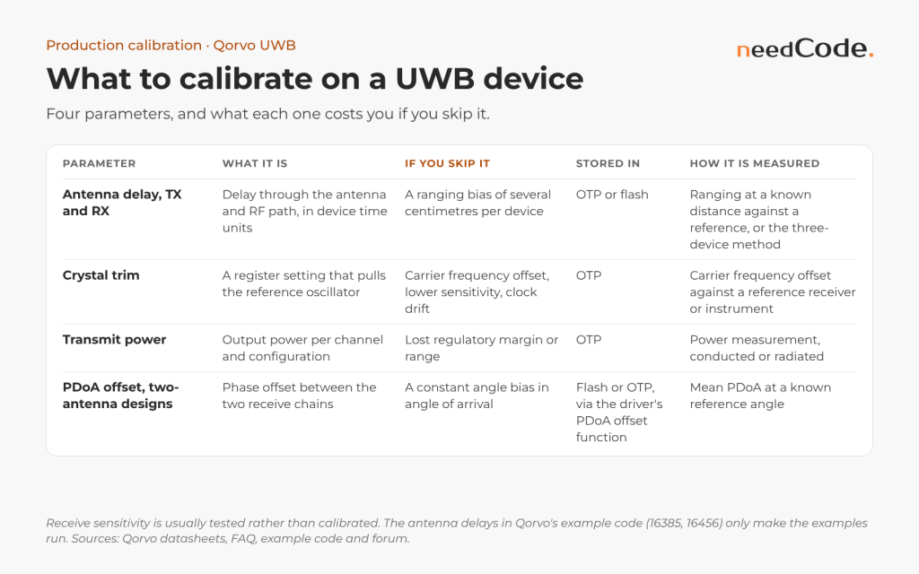
| Parameter | What it is | If you skip it | Where it is stored | How it is measured |
|---|---|---|---|---|
| Antenna delay (transmit and receive) | The delay through the antenna and RF path, in device time units | A ranging bias of several centimetres per device | OTP or flash | Ranging at a known distance against a calibrated reference, or the three-device method |
| Crystal trim | A register setting that pulls the reference oscillator | Carrier frequency offset, lower sensitivity, clock drift | OTP | Carrier frequency offset against a reference receiver or instrument |
| Transmit power | Output power per channel and configuration | Regulatory margin or range lost | OTP | Power measurement in a conducted or radiated set-up |
| PDoA offset (two-antenna designs) | Phase offset between the two receive chains | A constant angle bias in angle of arrival | Flash or OTP; set with the driver’s PDoA offset function | Mean PDoA at a known reference angle |
Receive sensitivity is usually tested rather than calibrated. For the DWM1000 module, Qorvo’s FAQ notes that “TX power and RX sensitivity are tested but not calibrated”, while the crystal is trimmed in production and its trim value is stored in OTP.
In Qorvo’s UWB stack these are L1 configuration keys: xtal_trim, ant<K>.ch<C>.ant_delay, ant<K>.ch<C>.ref_frame<R>.tx_power_index and ant_pair<P>.ch<C>.pdoa.offset. The antenna delay must be calibrated per antenna path and per channel used in the product.
Per unit or per design?
Qorvo’s guidance has been consistent since the DW1000. Its datasheet says antenna delay calibration “must be carried out as a once off measurement for each DW1000 design implementation” and that “for greater accuracy, antenna delay calibration should be carried out on each DW1000 PCB / module”. Comments in Qorvo’s DW3000 example code are more direct: “for a real production application, each device should have its own antenna delay properly calibrated”.
What modules ship with varies. A 2023 reply on Qorvo’s forum states that “the DWM3000 modules are not calibrated for antenna delay in production”, while the QM33110EVB evaluation board “is calibrated in the factory with antenna delay and txpower”. The DWM3000 datasheet confirms “no transmit power or antenna delay calibration”. DWM3001C modules differ: Qorvo staff state that they are factory calibrated for both, with values in OTP that the CLI’s RESTORE command restores. Do not assume a module or board is calibrated; check, and calibrate it yourself if you are not sure.
A practical rule:
| Application | Calibration approach |
|---|---|
| Proximity and presence, where 10–20 cm errors do not matter | Per-design antenna delay, verified on a sample of each batch |
| RTLS with sub-30 cm targets, digital key, secure access | Per-unit antenna delay, crystal trim and TX power |
| Angle of arrival with PDoA | Everything above, plus a per-unit PDoA offset |
Designing an end-of-line calibration station
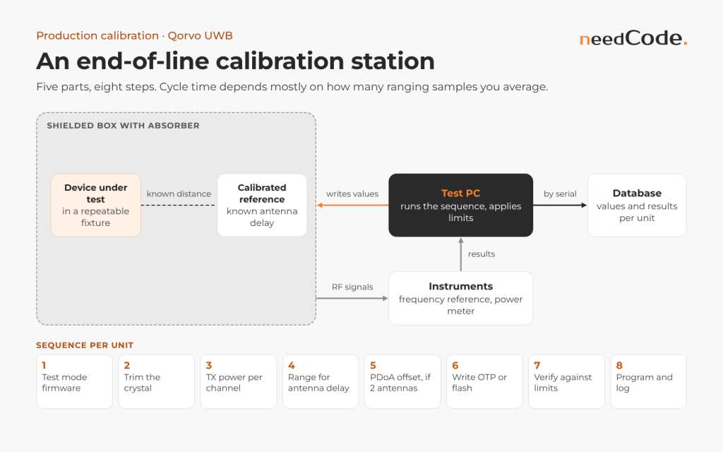
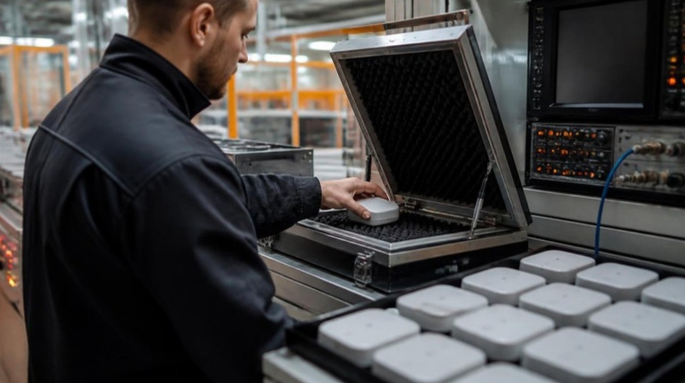
A calibration station has five parts:
- A fixture that holds the device under test in a repeatable position.
- A calibrated reference device at a known distance, inside an RF-controlled environment such as a shielded box with absorber, so reflections do not move the result.
- Instruments for the RF measurements: a frequency reference or a calibrated receiver for crystal trim, and a power meter or spectrum analyser for transmit power.
- A test PC that runs the sequence, applies limits and writes the results to the device.
- A database that links every serial number to its calibration values and test results.
A typical sequence:
- Program calibration firmware, or put the device into a test mode.
- Trim the crystal and store the trim value.
- Measure and set transmit power per channel in use.
- Range against the reference at the known distance and compute the antenna delay.
- For two-antenna devices, measure the PDoA offset at the reference angle.
- Write the values to OTP or flash.
- Verify: range again, check the result against pass/fail limits and re-check the angle.
- Program the production firmware and log everything against the serial number.
Why the order matters
- Crystal first. Qorvo’s example code calls single-sided TWR “highly sensitive to the clock offset error between the devices and the length of the response delay between frames”. An uncorrected 2 ppm offset over the 650 µs reply delay of Qorvo’s responder example biases the range by about 20 cm, which an antenna delay calibration would absorb. An IEEE Access study found this error “much less severe in SDS-TWR than in SS-TWR”, so range with DS-TWR.
- Power before delay. For a reference board, Qorvo staff advise to “first calibrate the transmit power to below regulatory levels and then calibrate the antenna delay”; the L1 specification requires the internal PA to be on during antenna delay calibration, typically at TX power index 24 (−6 dB).
- Write once. OTP cannot be rewritten, so check every value first and verify through the production firmware’s own load path.
Pass/fail checks
| Step | Pass/fail check |
|---|---|
| Crystal trim | Offset inside your limit (Qorvo trims DWM3000 modules to typically below 2 ppm); code not at a range end |
| Transmit power | PSD and peak below the regional limit minus your margin, per channel |
| Antenna delay | Spread and received level inside limits; delay inside the population window |
| PDoA offset | Spread inside limits; offset inside the population window |
| Storage | dwt_otpwriteandverify() returns DWT_SUCCESS; read-back matches |
| Verification | Mean range and angle error inside the final tolerance |
Sample size and cycle time
Averaging N measurements reduces random noise by roughly the square root of N, so N ≥ (z·σ/e)². With the datasheet’s σ of 15 mm, holding the mean within half a delay unit (2.35 mm) at z = 3 needs about 370 exchanges. Measure σ on your station, because the spread “increases with the actual range” (IEEE Access), and averaging cannot remove reflections or received-level bias. One forum user’s factory test takes 1,000 ranges with limits on spread and received power, then 250 to verify. Ranging time is N divided by the exchange rate, per channel and antenna path; the fixture, RF environment and instruments set the rest.
Cable or air? Calibrating over a coaxial cable removes the antenna from the measurement. That gives repeatable RF numbers, but the antenna’s contribution to the delay then has to come from a per-design value measured over the air. For products with integrated antennas, calibrate over the air.
Antenna delay: three methods
- Calibrated reference. The device under test ranges with a reference device whose antenna delay is already known, at a measured distance. The difference between measured and true distance gives the device’s delay. This is the most practical method for production; Qorvo’s L1 specification describes it with a reference test board in free space.
- Three-device method. Qorvo’s application note APS014, “Antenna Delay Calibration of DW1000-based Products and Systems”, is associated with a method that needs at least three devices ranging pairwise at known distances and searches iteratively for the delay values that fit all measurements. Qorvo staff describe its search: 1,000 candidate delay sets, the best 25% kept and perturbed in each of 100 iterations, “a minute or two” on a PC. It suits calibrating a first set of reference devices.
- Per-design value with sample checks. Measure a representative set of units, use the average for all units and verify a sample from each batch. It is cheaper, but it leaves the unit-to-unit spread in your error budget.
Procedure against a calibrated reference
- Fix distance, orientation, channel and antenna path; set transmit power first.
- Start from a known delay on TX and RX (the L1 default is 16405 units).
- Run N DS-TWR exchanges, logging range, received level and temperature.
- Reject outliers and take the median range error.
- Convert: one unit on both TX and RX moves the range by about 4.69 mm; a range that is too long needs a larger delay.
- Apply, range again and check the mean error before storing.
In a worked example from Qorvo staff, boards 7.914 m apart with zero delays reported 162.16 m, so each needed about 16438 units on TX and RX. An equal split only suits a pair. Otherwise use a calibrated reference, built from three devices (enough for a “golden board”, according to Qorvo staff) or from a larger set solved by least squares, as forum users do. An illustrative sketch:
/* Illustrative: per-unit antenna delay against a calibrated reference.
 * ranges_mm[]: N DS-TWR results with the DUT delay 'dly' set on TX and RX. */
#define MM_PER_UNIT 4.69f                  /* c x 15.65 ps */

uint16_t corrected_delay(const float *ranges_mm, int n, float true_mm, uint16_t dly)
{
    float err_mm = median_after_outlier_rejection(ranges_mm, n) - true_mm;
    long step = lroundf(err_mm / MM_PER_UNIT);     /* too long -> larger delay */
    return (uint16_t)(dly + step);
}

/* new_dly = corrected_delay(...); apply it, re-range, then store it */
dwt_settxantennadelay(new_dly);
dwt_setrxantennadelay(new_dly);
Example code is not a calibration. Qorvo’s DW3000 examples ship with a placeholder antenna delay of 16385 device units for transmit and receive, and Decawave’s DWM1001 SS-TWR initiator example uses 16456 for receive and 16300 for transmit. These numbers make the examples run; they are not values for your board.
Crystal trim
The DW3000 adjusts its crystal with a 6-bit trim setting that adds up to 8 pF of load capacitance in 0.125 pF steps. The datasheet describes a trimming range of typically ±20 ppm, and Qorvo specifies ±20 ppm crystals in line with the IEEE 802.15.4a standard. The DW1000 used a 5-bit setting with a range of about ±25 ppm. The trim value is stored in OTP, and Qorvo’s DW3000 driver also includes dwt_xtal_temperature_compensation(), which adjusts the trim with temperature from the crystal’s characteristics.
One detail matters for angle-of-arrival systems. The DW3000 datasheet states that “for optimal PDoA performance, a carrier frequency offset of greater than |5| ppm is required between devices”. Trimming every device to exactly the same frequency is therefore not always the goal in PDoA systems; follow Qorvo’s guidance for your part and use case.
Measuring the offset
- CW and an instrument.
dwt_configcwmode()supports crystal trimming; Qorvo’s example 04a uses channel 5, “the recommended channel for crystal trimming operation”. - GPIO0 clock. Forum users quote APS312: writing 0x3 to register 0x05:00 outputs a clock, 31.25 MHz on a DWM3001CDK according to Qorvo staff; one developer found it unstable.
- Reference receiver. Read
dwt_readclockoffset()on frames from a known-good transmitter; dividing by 2^26 gives the ratio. Qorvo’s example 02f trims this way and advises to “only adjust trimming at one end of a link”.
Measure at temperature equilibrium, which CW mode makes easier, according to a Qorvo answer.
Trim range and step size
Qorvo’s figures differ: about 1.5 ppm per step over 0x00–0x3F (API guide), about 0.8 ppm over 0x00–0x7F (L1 specification) and about 77 ppm in total with 4.7 pF capacitors (example 02f); staff call the DWM1000 step “not 100% linear”. Characterise each design from the CW frequency at both end codes, choose capacitors that centre the range, as the datasheet recommends, and find each unit’s code by measurement (illustrative):
/* Illustrative: find the trim code from two measurements, then refine.
 * measure_ppm(code): dwt_setxtaltrim(code), wait for settling, return the
 * median offset against the reference (instrument or dwt_readclockoffset()). */
uint8_t find_trim(uint8_t c0)
{
    uint8_t c1 = (c0 > 0x3B) ? c0 - 4 : c0 + 4;          /* 6-bit codes */
    float p0 = measure_ppm(c0), p1 = measure_ppm(c1);
    float slope = (p1 - p0) / ((float)c1 - (float)c0);   /* measured ppm per code */
    int c = (int)lroundf(c0 - p0 / slope);
    if (c < 0x00) c = 0x00;
    if (c > 0x3F) c = 0x3F;
    return best_of_neighbours(c);   /* try c-1, c, c+1; keep the smallest |ppm| */
}
Transmit power and spectral mask checks
Set each channel’s power as high as the regulations allow and no higher: for most regions a mean PSD of −41.3 dBm/MHz, measured as EIRP over the air for integrated antennas, according to the DWM3000 datasheet. US rules (47 CFR 15.521) define the mean as an RMS average in 1 MHz with 1 ms or less averaging; the 0 dBm peak in 50 MHz can be measured in a narrower bandwidth against 20 log(RBW/50) dBm, −24.4 dBm at 3 MHz.
Use continuous frame mode and confirm its period on the analyser: the API guide gives 124800 for 1 ms, while example 04b uses 249600. Qorvo staff report LO leakage with older DW3000 power settings, which “may cause some issues when you calibrate the TX power level”. Current SDKs use the TX power index instead: 0.25 dB per unit below maximum, per antenna path, channel and reference frame. A defined but uncalibrated reference frame transmits at maximum power, and on QM35 pa_gain_offset calibrates a typical 0–4 dB step at the PA switching point.
PDoA and angle-of-arrival calibration
Phase difference of arrival needs two antennas on the receiver: the QM33120W in Qorvo’s current portfolio, or the DW3120 and DW3220, which now have an end-of-life notice with a last time buy on 28 February 2027. The QM35825 offers four RF ports and 2D or 3D angle of arrival.
Each device has its own phase offset between the two receive chains. An answer on Qorvo’s forum describes the basic procedure: “At 0 degrees, take a set of a few hundred measurements and calculate the mean PDoA from that”, and notes that “the PDoA offset is calibrated for the PDoA values, not AoA”. Another forum answer explains that the offset spread “is mainly due to pcb and IC process variation as well as component variation”, so each node needs its own value. Qorvo’s driver provides a function to set the offset on the device.
The offset removes a constant bias. Mapping PDoA to angle across the full field of view also depends on antenna spacing, the product’s housing and nearby metal, so validate the angle curve per design across the angles you need.
PDoA offset procedure
- Place the reference at 0°; Qorvo’s QM35 tools ask for at least 1.5 m between devices.
- Collect a few hundred values in the production configuration. For the best spread (5° typical) the datasheet recommends PLEN 128 and STSLEN 256; at 5°, 300 samples give a standard error of about 0.3°.
- Average as angles:
dwt_readpdoa()returns radians with 11 fractional bits; use a circular mean if values approach ±π. - Store with
dwt_setpdoaoffset()or the Q11 keyant_pair<P>.ch<C>.pdoa.offset, then verify at 0° and one angle each side.
Qorvo’s UQT guide gives this QM35 sequence (comments added). Check key names with set_cal -l, and keep cables fixed, because cheap coax is “not phase stable”, according to Qorvo staff:
send_calset ranging_evb_pdoa_1_azimut                  # default calibration set
set_cal pdoa_lut0.data 'identity'                      # responder: identity LUT
run_fira_twr -c 5 -m ss -s 38 -p <port> --controlee    # shell 1: responder
run_fira_twr -c 5 -m ss -s 38 -p <port> --stats        # shell 2: read the 0° value
set_cal ant0.ch5.pdoa.axisx.offset $(python -c 'print(<x>*3.14/180)')
set_cal pdoa_lut0.data theory channel=5 antenna_dist_mm=20.8
Temperature and supply effects
Calibrate at a controlled temperature and record it. Then characterise the design across its operating range during validation, not on every unit. With the FAQ’s typical figure of 2.15 mm per °C, a device that works from −20 °C to +60 °C can drift by about 17 cm of reported range over that span unless software compensates. Supply voltage matters too, so calibrate at the nominal supply your product uses.
Storing calibration values: OTP or flash
The DWM3000 datasheet describes 128 × 32-bit OTP words “used to store per chip calibration information”. In Qorvo’s API guide map, production test owns words such as the chip and lot IDs, while the customer owns others, including the EUID (0x00–0x01), the crystal trim (0x1E), an OTP revision (0x1F) and unallocated blocks. The driver loads the trim from 0x1E and falls back to 0x2E, a default for 2 pF load capacitors, if it is empty. Place antenna delay and power in the customer area by your own layout and record its version in 0x1F. Programming is “a one-time only activity”, and writing outside designated areas “may permanently damage” the IC. An illustrative sketch:
/* Illustrative: write the crystal trim once and never overwrite it. */
#define OTP_XTAL_TRIM 0x1E
uint32_t word = 0;
dwt_otpread(OTP_XTAL_TRIM, &word, 1);
if ((word & 0x3F) == 0) {                          /* empty: not trimmed yet */
    if (dwt_otpwriteandverify(trim & 0x3F, OTP_XTAL_TRIM) != DWT_SUCCESS)
        station_fail("OTP 0x1E write");
} else if ((word & 0x3F) != trim) {
    store_trim_in_flash(trim);      /* OTP already programmed and cannot change */
}
SDK-based products set the same values as L1 keys with UQT (get_cal, set_cal, load_cal, reset_calibration) or the CLI’s CALKEY.
Statistical limits, outliers and traceability
Use the median and the median absolute deviation (MAD) per unit, and label samples as potential outliers when the modified Z-score, 0.6745(x − median)/MAD, exceeds 3.5 in absolute value, as Iglewicz and Hoaglin recommend in the NIST/SEMATECH handbook; if many are flagged, retest. Across units, set windows for trim code, delay and PDoA offset from a pilot build and track Cpk = min[(USL − μ)/3σ, (μ − LSL)/3σ], which NIST says needs about 50 independent values. A unit far outside the population usually has a hardware fault that calibration should not hide.
Key each record by serial number and EUI (Qorvo’s examples recommend buying EUI blocks from the IEEE Registration Authority), with IDs from dwt_getpartid() and dwt_getlotid() and die temperature from dwt_readtempvbat(). An illustrative record:
{
  "serial": "SN-000123", "eui64": "<OTP 0x00-0x01>",
  "chip": {"part_id": "<dwt_getpartid>", "lot_id": "<dwt_getlotid>", "otp_rev": 1},
  "software": {"station": "1.4.0", "fw": "2.0.1", "driver": "<dwt_version_string>"},
  "station": {"id": "EOL-02", "reference": "REF-3", "reference_checked": "2026-10-15"},
  "conditions": {"die_temp_c": 31.5, "ambient_c": 23.9, "supply_v": 3.30,
                 "distance_m": 2.000, "channel": 9, "antenna_path": 0},
  "xtal": {"initial_ppm": 6.1, "final_ppm": 0.4, "code": 31},
  "tx_power": {"index": "0x1A1A1A1A", "psd_dbm_mhz": -42.0, "peak_dbm": -1.9},
  "antenna_delay": {"n": 400, "median_mm": 2003.1, "mad_mm": 9.8,
                    "outliers": 3, "value": 16412},
  "pdoa": {"n": 300, "mean_rad": 0.211, "sd_deg": 4.6},
  "verify": {"n": 250, "mean_error_mm": 1.2},
  "storage": {"otp_0x1e": "DWT_SUCCESS"},
  "limits_version": "L-2026-10", "result": "PASS", "retests": 0,
  "timestamp": "2026-10-16T09:14:05Z"
}
Typical failures and how to confirm them
| Symptom | Likely cause | Confirm | Fix |
|---|---|---|---|
| Same error at every distance | Delay wrong or not loaded | Range at two distances | Recalibrate; check the load path |
| Bias differs between SS-TWR and DS-TWR | Crystal offset | dwt_readclockoffset() | Trim first |
xtal_trim reads 255 | Board never calibrated | get_cal xtal_trim | Production calibration |
| Delays shift when a jig unit is swapped | Reflections, cables | Rotate the jig | Fixed posts; least squares |
| Trim code at a range end | Wrong load capacitors | Offset at mid code | Fix the bill of materials |
Rows one, three and four come from Qorvo forum cases; in another, staff explain that a CLI listener application used driver_app_config.c defaults, not the stored keys.
Tools from Qorvo
- QM35 SDK: UQT, Python scripts that Qorvo positions for “evaluation, calibration, and manufacturing tests”. Its readme states that the scripts are not intended for production use, so use them to define the sequence and build your own station software.
- DW3_QM33 SDK: a command-line interface “for FiRa ranging, calibration/configuration and listener over Virtual COM Port”, according to Qorvo’s release notes for version 1.0.2. Staff point to
CALKEY,GETOTPandRESTOREfor calibration values. - Application notes: APS014 on antenna delay calibration, and the production test notes APS012 (DW1000), APS312 (DW3000) and APS512 (QM35), listed on Qorvo’s UWB application notes page alongside APS011 on TWR error sources and APS023 on transmit power calibration.
Keeping calibration valid in the field
Calibration can drift with ageing, repairs or housing changes. Log ranging residuals and angle statistics in the field, flag devices whose bias moves outside your limits, and define what triggers recalibration: a housing change, an antenna supplier change or a firmware change that touches timing.
A production calibration checklist
- Decide accuracy targets per product and choose per-unit or per-design calibration.
- Design the station: fixture, reference devices, RF environment and instruments.
- Calibrate the reference devices first, for example with the three-device method.
- Define the sequence, limits, OTP layout and data stored per serial number.
- Validate across temperature and supply range on a sample.
- Automate the station software and connect it to your manufacturing database.
- Monitor residuals in the field and define recalibration triggers.
From our engineering work
needCode’s UWB Precision Location Pack combines ranging algorithms, calibration tools and RTLS and access APIs for positioning below 30 cm. We verify TWR, TDoA and AoA on hardware-in-the-loop benches with robotic positioning, the same approach we used inside Qorvo’s UWB programme.
How needCode helps
We design calibration and production test flows for Qorvo-based devices: the station architecture, the test firmware and station software, the limits and the data model, and the validation across temperature and supply. For products moving from the DW1000 or from the DW3120 and DW3220, we include calibration in the migration plan.
Frequently asked questions
Do DWM3000 modules come calibrated from the factory?
Not for antenna delay, according to a 2023 reply on Qorvo’s forum: “The DWM3000 modules are not calibrated for antenna delay in production.” The same reply states that the QM33110EVB evaluation board is calibrated in the factory for antenna delay and transmit power. Check what your module or board includes and calibrate yourself if in doubt.
What ranging accuracy can I expect without calibration?
Qorvo’s DW3000 datasheet quotes about ±6 cm after calibration and roughly ±15 cm without it. Unit-to-unit variation, temperature and supply voltage add to the error, so production devices with sub-30 cm targets should be calibrated per unit.
What is the default antenna delay value?
There is no correct default for your board. Qorvo’s DW3000 example code uses a placeholder of 16385 device units, and Decawave’s DWM1001 initiator example uses 16456 (receive) and 16300 (transmit), so that the examples run. Qorvo’s own example comments say that each production device should have its own calibrated antenna delay.
How much does temperature affect UWB ranging?
Qorvo’s FAQ gives a typical figure of 2.15 mm of reported range per °C and 5.35 cm per volt of battery voltage. Over an 80 °C operating range that is about 17 cm unless software compensates, which is why calibration temperature should be controlled and recorded.
Do I need to calibrate PDoA on every unit?
Yes, for accurate angle of arrival. Answers on Qorvo’s forum explain that the PDoA offset varies with PCB, IC and component variation and recommend measuring the mean PDoA at 0° over a few hundred samples. The offset is set per device through the driver.
Can I calibrate antenna delay over a cable?
You can calibrate the RF path over a cable, but the antenna is then excluded. For products with integrated antennas, calibrate over the air or combine the cable result with a per-design antenna value measured over the air.
Where are calibration values stored?
In the chip’s one-time-programmable (OTP) memory or in the host’s flash. The DW3000 datasheet notes that OTP holds calibration data such as the transmit power level and the crystal’s initial frequency error adjustment, and Qorvo’s DW1000 datasheet notes that the antenna delay can be stored in OTP.
How many ranging samples does an antenna delay measurement need?
Size it from your station’s spread. With the datasheet’s 1.5 cm standard deviation, about 370 DS-TWR exchanges hold the mean within half a delay unit at three standard errors. Averaging never removes reflections or received-level bias.
Should the crystal be trimmed before antenna delay calibration?
Yes. Uncorrected single-sided TWR turns 2 ppm over a 650 µs reply delay into about 20 cm of bias, which the antenna delay would absorb. Trim first, range with DS-TWR and set transmit power before antenna delay.
Can a value written to OTP be corrected?
No. Qorvo’s API guide says that values programmed in error “cannot be corrected”. Check that a word is empty before writing, use only customer locations and keep values you may re-tune in flash.
Sources
- DW3000 datasheet v1.3 (Mouser copy)
- DW1000 datasheet v2.22 (university copy)
- Qorvo UWB FAQs
- Qorvo UWB application notes
- Qorvo Tech Forum: DW3000 antenna delay calibration in production
- Qorvo Tech Forum: calibration over an SMA cable on the QM33120WDK1
- Qorvo Tech Forum: PDoA calibration
- Qorvo Tech Forum: DWM3000 and APS014 calibration
- IEEE Access paper on antenna delay calibration of UWB nodes (PDF)
- Qorvo DW3000 example code, community Zephyr port and Decawave DWM1001 examples
- Qorvo DW3000 driver API (community copy of driver 08.02.02)
- Qorvo Tech Forum: “QM35 SDK 3.0 is now available” and QM35 SDK repository
- Qorvo Tech Forum: DW3_QM33 SDK v1.0.2 release
- Qorvo DW3120 product page (PCN 26-0105) and QM33120W product page
- Qorvo DW3xxx/QM33xxx Device Driver API Guide (forum attachment, April 2025)
- DWM3000 datasheet Rev B (Farnell copy)
- Qorvo UWB-Stack L1 configuration specification, July 2025 (QM35 SDK)
- Qorvo UWB Qorvo Tools guide, release 13.1.0 (QM35 SDK)
- Qorvo DW3000 example 02f, RX with crystal trim, 04a, continuous wave, 04b, continuous frame, 06b, SS-TWR responder and shared definitions (community Zephyr port)
- Qorvo Tech Forum: XTAL trimming on DW3000 chips and GPIO clock XTAL calibration method
- Qorvo Tech Forum: DWM1000 crystal trimming resolution and PDoA average trim per pphm
- Qorvo Tech Forum: DWM3000 as an antenna delay reference test board
- Qorvo Tech Forum: DW3000 LO leakage and debug.tx_power and tx_power_index
- Qorvo Tech Forum: reducing distance error on the DWM3001CDK and factory-calibrated xtal_trim and the SDK
- Qorvo Tech Forum: RangingTxFailed and xtal_trim on a custom design, Calibration issues with UWB and DWM3000 antenna delay calibration error
- NIST/SEMATECH e-Handbook: Detection of outliers and What is process capability?
- 47 CFR 15.521, technical requirements applicable to all UWB devices (eCFR)
About needCode
needCode is an independent embedded engineering company from Kraków, Poland, and an official UWB business partner of Qorvo. Its engineers have worked inside Qorvo’s wireless programmes for more than eight years, including on the public QM35 SDK. needCode is certified to ISO 9001:2015 and ISO/IEC 27001:2022 and is a member of the UWB Alliance. This article does not represent Qorvo. All trademarks belong to their respective owners.