
Facts checked on 16 October 2026
Short answer
Qorvo staff wrote in June 2026 that “the DWM3001C is just as capable as the LEAPS kit in making a TDoA system”, and in August that nothing is available from Qorvo for it, publicly or under NDA.
That leaves four starting points: evaluate with the QM33120WDK2 and LEAPS software, license a partner stack, build your own on the DW3_QM33 driver, or move to the QM35825 with FiRa DL-TDoA. The result then depends on uplink or downlink, clock synchronisation, timestamp quality, solver and anchor geometry, airtime and tag energy.
What Qorvo provides, and what it does not
Most teams arrive here with two-way ranging (TWR) working on the DWM3001CDK and a need for more tags than TWR can serve. The table shows what Qorvo has said on its forum, product pages and SDK documentation.
| Item | Status | Source and date |
|---|---|---|
| TDoA example for the DWM3001C | None: “Nothing is available from Qorvo for DWM3001C either publicly or through NDA” | Qorvo staff, August 2026 |
| TDoA in the DW3_QM33 SDK | “The Qorvo QM33 SDK does not support TDoA use cases. However, the chipset is capable of it” | Qorvo staff, July 2026 |
| QM33 uplink TDoA tag software | “a QM33 UT-Tag SDK available through NDA” | Qorvo staff, August 2026 |
| FiRa MAC source code | “We do not provide source code to the FiRa MAC.” | Qorvo staff, August 2026 |
| QM33120WDK2 kit | Evaluates DL-TDoA, UL-TDoA and TWR with software developed by partner LEAPS | Qorvo product page; Qorvo staff, August 2026 |
| QM35825 with the QM35 SDK | FiRa DL-TDoA anchor and tag; Qorvo gives “the timestamps but not the location algorithm” | Qorvo staff, June and September 2026 |
| QM35825 DL-TDoA data for the host | Per anchor message: TX and RX timestamps (ticks of about 15.65 ps), frequency offset, anchor location, NLOS flags | Qorvo Cherry API guide, July 2025 |
| External clock on the DW3110 | “supports using an external 38.4 MHz reference clock in place of the crystal” | Qorvo staff, September 2026 |
The pattern is consistent. Qorvo provides the radio, the driver and accurate timestamps. Synchronisation, the TDoA MAC, the solver and the tools are yours or a partner’s.
UL-TDoA or DL-TDoA?
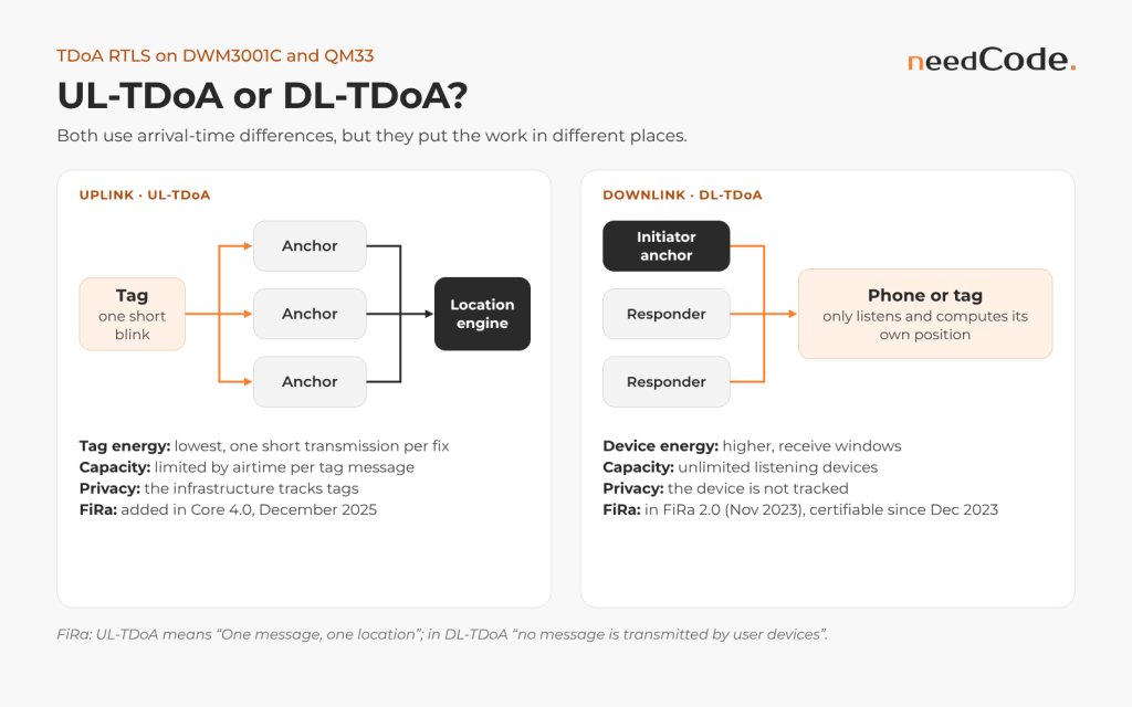
Both methods use arrival-time differences, but they put the work in different places.
| UL-TDoA (uplink) | DL-TDoA (downlink) | TWR, for comparison | |
|---|---|---|---|
| Who transmits | The tag sends short messages | Anchors exchange messages | Tag and each anchor |
| Who computes the position | A location engine fed by the anchors | The tag or phone itself | Tag or server |
| Anchor synchronisation | Required | Required, carried in the anchor messages | Not required |
| Capacity | Limited by airtime per tag message | Unlimited listening tags | Limited by airtime per exchange |
| Tag energy | Lowest: one short transmission per fix | Higher: receive windows | Highest: several exchanges per fix |
| Privacy | The infrastructure tracks tags | The device is not tracked | Both sides see distances |
| FiRa roles | UT-Tag, UT-Anchor and a UT synchronisation role | DT-Anchor, DT-Tag | Initiator, responder |
| FiRa | Added to specification and certification in FiRa Core 4.0, December 2025 | In FiRa 2.0 (November 2023); certifiable since December 2023 | Since FiRa 1.0 |
FiRa summarises uplink TDoA as “One message, one location”: each tag transmission gives one position. FiRa describes downlink TDoA as untracked navigation, where “no message is transmitted by user devices”. Qorvo’s FiRa stack requires static STS, built on a publicly known key, for both TDoA modes.
Asset tracking with many small tags favours UL-TDoA. Navigation and phones favour DL-TDoA, now supported by iPhone and Android APIs.
What each method measures
In uplink TDoA every anchor timestamps the same blink, and each synchronised anchor pair gives a range difference. The tag’s transmit time and antenna delay cancel; the anchors’ delays and sync errors do not. In downlink TDoA, Qorvo’s FiRa documentation pairs anchor transmit timestamps in the cluster’s common time base with tag receive timestamps, so the unknown offset between the two cancels. The tag’s clock rate does not, so the UTIL paper’s formulation scales anchor intervals by a correction factor α.
UL-TDoA: anchors i and j timestamp one blink (reference time base)
  d_ij = c * (T_i - T_j) = |p - a_i| - |p - a_j|

DL-TDoA: tag receives anchors i and j (Qorvo FiRa DL-TDoA notation)
  D_i - D_j = c * (T'RX_i - T'RX_j + TTX_j - TTX_i)
  T'RX = receive time, tag clock;  TTX = transmit time, common time base

Tag clock correction from two packets of anchor j (UTIL paper)
  alpha = (trx_j - trx_j_prev) / (ttx_j - ttx_j_prev)
Clock synchronisation: the core of every TDoA system
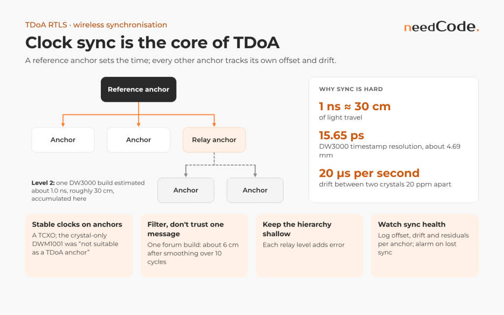
TDoA compares times measured by different clocks, so the clocks must agree. Light travels about 30 cm in 1 ns. Qorvo’s DW3000 timestamps resolve about 15.65 ps, roughly 4.69 mm, but two crystals that differ by 20 ppm drift apart by 20 µs every second. The system must therefore track each anchor’s offset and drift continuously.
| Approach | How it works | Strengths | Weak points |
|---|---|---|---|
| Wired clock distribution | Anchors share one reference clock over cable | Removes drift between anchors | Cabling cost, cable delays that change with temperature, installation effort |
| Wired sync pulse | A common pulse marks a time instant for all anchors | Simple concept | Pulse timing accuracy rarely reaches the picosecond level TDoA needs |
| Wireless sync | A reference anchor transmits; other anchors estimate offset and drift from its messages and the known time of flight | No extra cabling; the method used in the QM33120WDK2 software and in Qorvo’s QM35 DL-TDoA | Needs careful filtering, anchor geometry and a sync hierarchy |
Qorvo’s own evidence points to wireless sync. Qorvo staff wrote in August 2026 that “the QM33120WDK2 is doing wireless clock synchronization”. For the QM35, Qorvo describes “in-band synchronization”: one anchor acts as the reference initiator and responders in a cluster sync to its local time.
The Decawave team, now part of Qorvo, also published a comparison of wireless clock synchronisation algorithms for TDoA: linear interpolation, PI, PID, PII and Kalman filters. Qorvo still hosts the paper. Partner Ciholas went further on Qorvo’s forum, calling an anchor array with a wired distributed clock “basically unworkable”.
Practical rules from Qorvo and forum experience:
- Use a stable reference on anchors. In 2019 Decawave staff wrote that “using a TXCO is required in the system” for precise synchronisation, which is why the crystal-based DWM1001 was “not suitable as a TDoA anchor”.
- Filter, don’t trust single sync messages. One engineer on Qorvo’s forum reported position errors of about 6 cm after smoothing clock offset and drift over 10 cycles.
- Keep the sync hierarchy shallow. Each relay level adds error. A forum author who built DL-TDoA on the DW3000 estimated about 1.0 ns accumulated at the second level, roughly 30 cm.
- Watch sync health in operation. Log offset, drift and residuals per anchor, and alarm when an anchor loses sync.
What a sync packet carries
Decawave’s open-source uwb-core, written for the DW1000, is the most detailed public reference. A clock master sends clock calibration packets (CCP) carrying its transmit timestamp. “Precise timing is achieved by adding a fixed period to the transmission time of the previous frame”, so operating-system latency does not matter. The default period is about 1.08 s, relays repeat packets over up to four levels, and each receiver subtracts the master’s time of flight and records the carrier integrator, a frequency-offset reading. Decawave’s timescale library quotes “1-sigma 30 DTUs (~500ps)” with a 1 s period, about 15 cm.
In FiRa DL-TDoA, Qorvo’s documentation has each responder compute its offset from the initiator’s Poll as T′RxPoll − (TTxPoll + ToF), estimate the frequency offset in hardware (SS-TWR) or from the Poll-to-Final interval (DS-TWR), then convert its transmit timestamps to the common time base. The optional DL_TDOA_HOP_COUNT stops sync loops: anchors accept sync only from a lower hop count.
Interpolation or Kalman filter
Decawave’s comparison used ±1 ppm TCXOs in a 6.5 × 6.5 × 2.7 m room, sync packets every 150 ms, and longer periods made by decimating the same recording. The measured drift was “~-0.2 ppm (a change of about -31ns over a 150ms period)”, and timestamp noise was 100–150 ps.
| Sync period | Interpolation, R95 horizontal | Kalman, R95 horizontal | Pass rate, interpolation / Kalman |
|---|---|---|---|
| 150 ms | 14.6 cm | 11.3 cm | 97.8% / 99.7% |
| 900 ms | 20.2 cm | 20.7 cm | 79.9% / 98.9% |
Interpolation waits for the next sync packet, which adds latency, and loses fixes at long periods; the two-state Kalman filter (arrival time and skew) avoids both. The illustrative sketch below starts from Decawave’s tuned noise values.
/* Illustrative: per-anchor clock filter. Times in seconds, unwrapped
 * from 40-bit timestamps with ts40_diff(). State: offset, skew. */
#define R_TOA 3e-20   /* s^2, Decawave's tuned measurement noise */
#define Q_T   5e-20   /* s^2, Decawave's tuned process noise */
#define Q_S   1e-18   /* skew random walk: tune for your oscillator */

typedef struct { double off, skew, P[2][2], t_prev; } clk_t;

void clk_on_sync(clk_t *k, double t_rx_loc, double t_tx_master, double tof)
{
    double dt  = t_rx_loc - k->t_prev;
    double off = k->off + k->skew * dt;                 /* predict */
    double P00 = k->P[0][0] + dt * (k->P[0][1] + k->P[1][0])
               + dt * dt * k->P[1][1] + Q_T;
    double P01 = k->P[0][1] + dt * k->P[1][1];
    double P11 = k->P[1][1] + Q_S;
    double y   = (t_rx_loc - (t_tx_master + tof)) - off; /* innovation */
    double S   = P00 + R_TOA;
    if (y * y > 25.0 * S) return;           /* 5-sigma gate: skip packet */
    double K0 = P00 / S, K1 = P01 / S;
    k->off  = off + K0 * y;
    k->skew = k->skew + K1 * y;
    k->P[0][0] = (1 - K0) * P00;  k->P[0][1] = (1 - K0) * P01;
    k->P[1][0] = k->P[0][1];      k->P[1][1] = P11 - K1 * P01;
    k->t_prev = t_rx_loc;
}

double clk_to_master(const clk_t *k, double t_loc)   /* map a blink time */
{
    return t_loc - (k->off + k->skew * (t_loc - k->t_prev));
}
Timestamp quality
Synchronisation only helps if the timestamps are right. Five things matter:
- Antenna delay calibration on every anchor, because a delay error becomes a position bias. Qorvo’s FAQ notes that it varies “slightly between different units of the same design”, and anchors also receive sync packets, so calibrate both directions.
- First-path detection in reflections and non-line-of-sight conditions. In April 2026 a team on Qorvo’s forum reported TDoA distances on the DW3000 that “flip between two stable basins about 120cm apart”; the thread is unanswered. Test for such effects deliberately. In the UTIL dataset, static obstacles caused repeatable biases and moving ones “less predictable” errors.
- Temperature. Qorvo’s FAQ, quoting the DW1000 User Manual, gives a typical ranging change of 2.15 mm per °C (and 5.35 cm per volt of battery voltage), so anchors in unheated halls need compensation or regular sync updates.
- Timestamp width. Timestamps are 40-bit counts of ticks of about 15.65 ps (FiRa TDoA messages also allow 64-bit), so they wrap every 17.2 s: subtract modulo 2^40.
- Scheduled transmit times. Community code on Qorvo’s forum shows the DW3000 pattern for embedding a transmit time: clear the ignored lowest bit of the 32-bit delayed-transmit value, shift it back by 8 bits and add the TX antenna delay.
/* Signed difference a - b of two 40-bit timestamps (ticks of ~15.65 ps) */
static inline int64_t ts40_diff(uint64_t a, uint64_t b)
{
    int64_t d = (int64_t)((a - b) & 0xFFFFFFFFFFULL);
    return (d >= (1LL << 39)) ? d - (1LL << 40) : d;
}
The position solver
Neither Qorvo SDK computes positions. Qorvo’s QM35 SDK documentation states that the multilateration algorithm “has to be implemented in the host application”. For the DW3000 and QM33, Qorvo staff say the same: “We give you the timestamps but not the location algorithm, that is on the end user to develop.”
A production solver has four parts:
- Measurement model: time differences between anchor pairs, corrected for sync and calibration.
- Estimator: a closed-form start followed by iterative least squares, or a Kalman or particle filter for moving tags.
- Outlier handling: reject measurements with large residuals and down-weight anchors in non-line-of-sight.
- Geometry checks: flag positions outside the anchors’ coverage, where dilution of precision grows.
Anchor count and placement drive accuracy as much as code. Ciholas, a Qorvo partner, wrote that “using 6 anchors would be the lowest we would recommend and 8 would produce a reasonable output if you aren’t too concerned about Z axis”.
Gauss–Newton, step by step
With one reference anchor, form d_i0 = c·(T_i − T_0); the Jacobian rows are differences of unit vectors, the linearisation Zhao, Goudar and Schoellig use for placement analysis. Start from the previous fix or the centroid of the anchors that heard the blink. Differences against one reference share its noise, so weight them accordingly. An illustrative sketch:
# Illustrative Gauss-Newton TDoA solver (NumPy).
# A: N x 3 anchor positions [m], row 0 = reference anchor
# d: N-1 measured differences d_i0 = c * (T_i - T_0) [m]; p: start [m]
def solve_tdoa(A, d, p, iters=10):
    for _ in range(iters):
        r = np.linalg.norm(A - p, axis=1)      # ranges to all anchors
        u = (p - A) / r[:, None]               # unit vectors, anchor -> tag
        J = u[1:] - u[0]                       # Jacobian rows, (N-1) x 3
        dp = np.linalg.lstsq(J, d - (r[1:] - r[0]), rcond=None)[0]
        p = p + dp
        if np.linalg.norm(dp) < 1e-3:
            break
    r = np.linalg.norm(A - p, axis=1)
    resid = d - (r[1:] - r[0])                 # feed to the outlier gate
    gdop = np.sqrt(np.trace(np.linalg.inv(J.T @ J)))
    return p, resid, gdop
Geometry, GDOP and gating
For Gaussian noise the Fisher information is JᵀJ/σ², so the best achievable covariance is σ²(JᵀJ)⁻¹, and the square root of its trace over σ is the GDOP known from GPS. Bitcraze’s rule of thumb: accuracy is good inside the anchors’ convex hull and “deteriorates quickly when moving away outside”. Height spread matters: in tests by Zhao et al., the same four anchors gave 21 cm RMSE on 2.65 m tripods and 16 cm with 5.5 m of vertical separation.
Gate before and after solving. Bitcraze discards any TDoA larger than the distance between its two anchors and checks sequence numbers; Zhao et al. tested residuals with a Mahalanobis threshold of 5, raised to 10 in a cluttered multi-room site.
Error budget
At about 30 cm per nanosecond, timing terms map directly onto range difference; random terms then scale with GDOP, and biases do not average out.
| Term | Typical size | Range-difference effect |
|---|---|---|
| Timestamp noise, line of sight | 100–150 ps (DW1000) | 3–4.5 cm |
| Residual sync error | About 500 ps (1σ) at a 1 s period | About 15 cm |
| Skew error of 1 ppb | 150 ps in 150 ms; 1 ns in 1 s | 4.5 cm; 30 cm |
| Anchor temperature | 2.15 mm per °C (DW1000 ranging figure) | 4.3 cm over 20 °C |
| Anchor coordinates | 22 cm RMSE when placed from drawings | Enters directly |
| NLOS and multipath | 28 cm measured vs a 17 cm bound at one site | Site-specific |
Anchor placement and survey procedure
Geometry, sync links and surveyed coordinates set a floor no solver can beat. A procedure based on the published studies:
- Plan. Put anchors on the boundary so tag areas lie inside their convex hull, keep 5–10 anchors in range of every point (Bitcraze’s design target) and add vertical spread where height matters.
- Predict. Compute a GDOP or Cramér–Rao map along the tag paths. Zhao et al. measured 28 cm against a 17 cm bound and recommend a conservative noise value. Pass: the predicted error meets the requirement everywhere.
- Check sync links. Each anchor needs line of sight to its sync source, as in Zhao et al.’s staircase deployment. Pass: logged sync reception meets your threshold over a working day.
- Survey. Use a millimetre-accurate total station, with the frame defined from two surveyed points; Zhao et al.’s installed anchors differed from the design by 22 cm RMSE, partly because the building did not match its blueprints. Survey antenna centres, and orientation too if errors depend on pose.
- Calibrate antenna delays per unit and store them with the coordinates.
- Verify on static points. Pass: bias and R95 within the requirement everywhere, with no anchor showing a persistent residual.
Capacity and update rates
Airtime limits uplink TDoA and TWR, not the number of tags you sell. LEAPS publishes capacity figures for its RTLS: a maximum density of 320 Hz for TWR, 600 Hz for UL-TDoA “or an unlimited amount of Tags when DL-TDoA is used”. In practice that means:
| Mode | Total capacity (LEAPS figure) | Example split |
|---|---|---|
| TWR | 320 location updates per second | 32 tags at 10 Hz |
| UL-TDoA | 600 location updates per second | 60 tags at 10 Hz, or 600 tags at 1 Hz |
| DL-TDoA | Unlimited tags | Every tag at the anchors’ update rate; LEAPS quotes up to 50 Hz |
These numbers belong to one stack and one configuration; your own MAC sets your limits. For comparison, a developer on Qorvo’s forum measured “a practical ceiling of roughly 8-10 concurrent tags per anchor cell” with TWR on the DWM3001CDK before the update rate degraded. Motion-dependent rates help everywhere: a resting asset does not need 10 updates a second.
Airtime arithmetic for uplink blinks
The DW3000 datasheet gives the symbol timings at 64 MHz PRF: 1017.63 ns per preamble or SFD symbol, 1025.64 ns per PHR symbol at 850 kbps and 128.21 ns per data bit at 6.81 Mbps, plus 48 Reed–Solomon parity bits per 330 data bits. A 64-symbol preamble, 8-symbol SFD, 21-symbol PHR and 12-byte payload take 73.3 + 21.5 + 18.5 ≈ 113 µs, close to the “around 110 µs” in Qorvo’s FAQ.
Blinks sent at random times can overlap. Abramson’s ALOHA analysis gives the overlap probability at a total rate λ as 1 − exp(−2λT). For T = 113 µs:
| Total blinks per second | Channel occupancy | Blinks without overlap |
|---|---|---|
| 44 | 0.5% | 99% |
| 227 | 2.6% | 95% |
| 466 | 5.3% | 90% |
| 1,000 | 11.3% | 80% |
FiRa UL-TDoA tags get a transmit interval and a random window (UL_TDOA_TX_INTERVAL, UL_TDOA_RANDOM_WINDOW in Qorvo’s UCI specification; Android’s UWB stack defaults to 2,000 ms and 0 ms). In DL-TDoA the anchors’ schedule sets the rate: with Qorvo’s defaults of 2,400 RSTU slots (1,200 RSTU is 1 ms) and 25 slots per round, a round lasts 50 ms however many tags listen.
Tag energy
The DW3000 cannot transmit on its own schedule: Qorvo staff confirmed that “the DW3000 needs a host MCU to configure it”. Every uplink blink therefore wakes the host, configures the radio, transmits and returns to sleep. The DWM3001C, with its integrated nRF52833, suits such tags. Downlink tags avoid transmitting but must open receive windows that match the anchors’ schedule, so their energy depends on how precisely they track the anchors’ timing.
The DW3000 datasheet profiles a “6.8Mbps TDoA tag frame” (channel 5, 128-symbol preamble, 12 bytes, 3.0 V): mainly 1,000 µs of oscillator start-up at 1.5 mA, 135 µs of preamble at 48 mA and 16 µs of header and payload at 40 mA, then deep sleep at 260 nA. That is about 9 µC per blink, or 9 µA average at 1 Hz before the host MCU’s share. Its single-frame receive profile comes to about 12.6 µC, so a downlink fix from six anchor messages costs at least 75 µC.
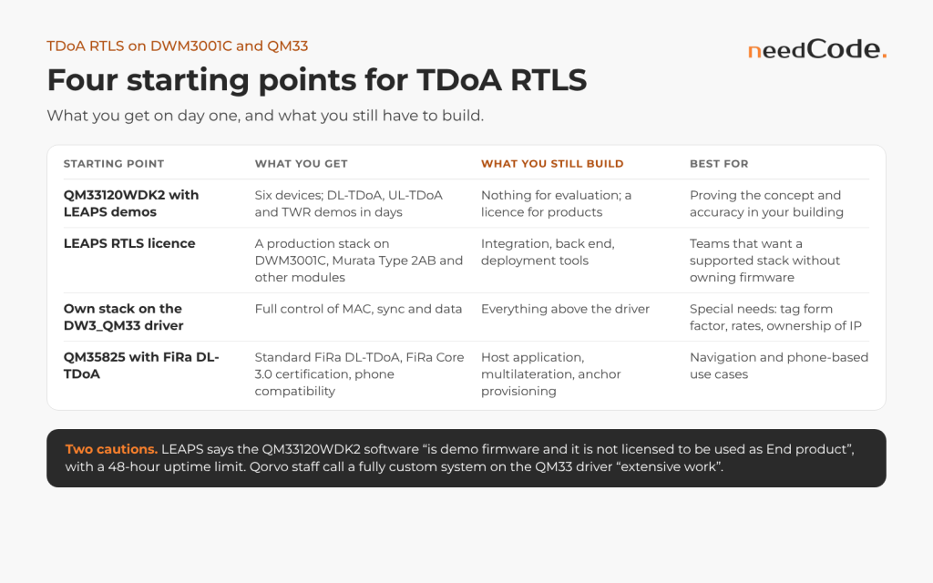
Four starting points
| Starting point | What you get | What you still build | Best for |
|---|---|---|---|
| QM33120WDK2 with LEAPS demos | Six devices; DL-TDoA, UL-TDoA and TWR demos in days | Nothing for evaluation; a licence for products | Proving the concept and the accuracy in your building |
| LEAPS RTLS licence | A production stack on DWM3001C, Murata Type 2AB and other modules | Integration, backend, deployment tools | Teams that want a supported stack without owning firmware |
| Own stack on the DW3_QM33 driver | Full control of MAC, sync and data | Everything above the driver | Products with special needs: tag form factor, rates, ownership of IP |
| QM35825 with FiRa DL-TDoA | Standard FiRa DL-TDoA, FiRa Core 3.0 certification, phone compatibility | Host application, multilateration, anchor provisioning | Navigation and phone-based use cases |
Two cautions apply. LEAPS states on Qorvo’s forum that the software supplied with the QM33120WDK2 “is demo firmware and it is not licensed to be used as End product”, with a 48-hour uptime limitation. And Qorvo staff call a fully custom system on the QM33 driver “extensive work”. Plan its MAC, sync and test tooling as a project of its own.
First sessions on the evaluation kits
LEAPS documents a shell set-up for its UL-TDoA demo (profile 5): at least five LC14 devices, a Raspberry Pi per anchor running the LEAPS Gateway, positions published over MQTT, and no auto-positioning.
# LEAPS UL-TDoA demo, serial shell at 115200 baud (from the LEAPS docs)
leaps> nps 5          # every device: profile 5 (UL-TDoA); nis 0x1234; reset
leaps> nmi            # one anchor: initiator; others: nma; tag: nmt
leaps> acs cr 1       # one anchor: enable clock reference, then reset
leaps> ps 3000 0 0    # each anchor: set position (example values)
leaps> tcs mode 1     # tag: UL-TDoA mode, then reset
leaps> urs 1 1        # tag: 0.1 s update interval, moving and stationary
leaps> la             # list anchors in range: id, seat, clk_lvl, pos
Pass check: la on the initiator lists every anchor, with clk_lvl=0 on the initiator and 1 on the others in LEAPS’s example. On the QM35, Qorvo’s run_fira_dt script sets up the smallest DL-TDoA system with three boards:
# QM35 SDK, UWB-Qorvo-Tools run_fira_dt README; one shell per board
run_fira_dt -t -1 --role=dt-anchor --mac="12:34" --role-per-round="[(0,init)]" \
    --dest-per-slot="[ (0, [(0xabcd,), ]) ]" --is-time-ref
run_fira_dt -t -1 --role dt-anchor --mac="ab:cd" --role-per-round "[(0,resp)]"
run_fira_dt -t -1 --role dt-tag --mac="00:b1" --activity="[0]"
Pass check: the tag reports OwrDltdoa measurements with status Ok for both anchors.
A test plan for TDoA
- Ground truth: measure static grid points and moving tracks against a reference, ideally with robotic positioning so tests repeat exactly. The UTIL team used one-minute static captures; Zhao et al. tracked walkers with a total station at 5 Hz.
- Metrics: bias, RMSE, R95 and pass rate per point, compared with the theoretical bound for the layout. Decawave’s R95 ignores fixed bias, so report bias separately.
- Sync stability: run anchors over temperature and over days, and log offset, drift and lost-sync events. Record at the shortest sync period and decimate offline, as Decawave did, so every filter sees identical data.
- Capacity: load the system with the target number of tags at the target rates and watch latency and lost fixes against the ALOHA prediction.
- Faults: remove anchors, block lines of sight, add metal and people, both static and moving.
- Protocol evidence: capture the air interface with a UWB sniffer to see which message failed, not only that a position is wrong.
Typical failures
| Symptom | Likely cause | How to confirm | Fix |
|---|---|---|---|
| Anchor offset jumps at random (forum report) | Mixed 32- and 40-bit values or a wrap bug | Raw 40-bit log: offset should drift steadily | Modulo-2^40 arithmetic |
| Error grows between sync packets | Drift model or sync period | Decimate a recording and compare | Shorter period, Kalman filter, TCXO |
| One pair flips by about 120 cm (forum report) | First-path ambiguity | Histogram per pair; CIR | Gate the pair; review mounting |
| Constant offset in one zone | Antenna delay, coordinates or static NLOS | Residuals per anchor | Recalibrate or re-survey |
| Fixes drop as tags are added | Blink collisions | Received against sent blinks | Lower rates, random window |
| Anchors lose sync together | Single sync path | Sync source per anchor | Redundant paths, hop count |
From our engineering work
Inside Qorvo’s UWB programme, needCode engineers developed an RTLS using TDoA algorithms and verified TWR, TDoA and AoA on hardware-in-the-loop stands with custom robotics. Our Autopositioning Anchors building block places anchors automatically: only the master anchor needs a known reference point and orientation, the others calculate their own positions, and the anchors connect over Wi-Fi and can run on batteries.
How needCode helps
We design and build TDoA systems on Qorvo silicon: the choice between uplink and downlink TDoA, anchor synchronisation, the TDoA MAC on the DW3_QM33 driver or FiRa DL-TDoA on the QM35825, the position solver and the test benches that prove accuracy and capacity. For teams starting from a TWR prototype, we begin with an assessment of the hardware, the target tag count and the deployment, and end with a plan for evaluation, licensing or custom development.
Frequently asked questions
Is there a TDoA example for the Qorvo DWM3001C?
No. In June 2026 Qorvo staff wrote that “we (Qorvo) don’t have any example to use as a starting point” and pointed to Qorvo’s partners. In August 2026 they added that nothing is available for the DWM3001C, publicly or under NDA.
Can the DWM3001C be used for TDoA at all?
Yes. Qorvo staff wrote that “the DWM3001C is just as capable as the LEAPS kit in making a TDoA system”. FiRa also lists a DL-TDoA prototyping kit from Pinpoint that names the DWM3001C as its FiRa-certified chip. The software comes from a partner or from your own team.
How do I synchronise clocks between UWB TDoA anchors?
Most systems use wireless synchronisation: a reference anchor transmits and the others estimate their offset and drift from its messages and the known time of flight. Qorvo’s QM33120WDK2 software and the QM35 DL-TDoA implementation both work this way. Wired clocks are possible, and the DW3110 accepts an external 38.4 MHz reference, but cabling adds cost and temperature effects.
How often should TDoA anchors exchange sync packets?
It depends on the oscillator and the filter. With ±1 ppm TCXOs, Decawave’s Kalman filter held the horizontal R95 at 11.3 cm with a 150 ms period and 20.7 cm at 900 ms; its open uwb-core defaults to about 1.08 s. Check by multiplying skew error by period: 1 ppb over 1 s is 30 cm.
How many anchors does a TDoA system need?
At least four in range for a 3D fix and three for 2D. Practical systems use more: Bitcraze designs for 5–10 anchors in range of a tag, and Ciholas recommends no fewer than six. Check the GDOP map before installing.
Should I use UL-TDoA or DL-TDoA?
Use UL-TDoA when the infrastructure must track many low-power tags, such as assets or people in a plant. Use DL-TDoA when devices should know their own position without being tracked, for example phones navigating a building. FiRa now covers both: DL-TDoA since FiRa 2.0 and UL-TDoA since FiRa Core 4.0.
Can I use the QM33120WDK2 software in my product?
Not as supplied. LEAPS, which developed the kit’s software, states that it is demo firmware “not licensed to be used as End product” and limited to 48 hours of uptime. Licensing for products is discussed with LEAPS.
Does Qorvo’s QM35 SDK compute positions for DL-TDoA?
No. The QM35825 firmware provides FiRa DL-TDoA timestamps and anchor synchronisation, and the SDK documentation states that multilateration has to be implemented in the host application.
Sources
- Qorvo Tech Forum: “Success with DWM3001 TDoA firmware?” (staff reply, June 2026)
- Qorvo Tech Forum: “DWM3001CDK — availability of TDoA example / reference code” (staff reply, August 2026)
- Qorvo Tech Forum: wireless anchor clock sync for custom TDoA (staff reply, July 2026)
- Qorvo Tech Forum: DW3_QM33 SDK v1.0.2 thread, post on DT-Tag support (June 2026)
- Qorvo Tech Forum: FiRa MAC source code (August 2026), external clock on the DW3110 (September 2026) and DW3000 without host MCU (December 2025)
- Qorvo QM33120WDK2 product page and LEAPS UDK demos
- LEAPS RTLS Specification v1.0 (August 2024) and Qorvo Tech Forum: QM33120WDK2 demo firmware licensing (January 2026)
- Qorvo Tech Forum: QM35825 DL-TDoA time sync (September 2025) and Qorvo QM35 SDK repository
- Decawave: Comparison of wireless clock synchronization algorithms for indoor location systems (hosted by Qorvo)
- Qorvo Tech Forum: “DWM1004C TDoA Tags” (Decawave staff, 2019) and “Source code for TDOA”
- FiRa: UWB Asset Tracking leaflet (2023), Untracked Indoor Navigation (2023) and FiRa Core 4.0 release (December 2025)
- FiRa: QM35825 Core 3.0 certification (July 2025) and FiRa 2.0 prototyping kit by Pinpoint
- Forum reports cited as user experience: anchor sync smoothing (July 2026), DIY downlink TDoA (May 2026), bimodal timestamp flips (April 2026), TWR tag ceiling (August 2026) and anchor density (April 2026)
- Decawave open-source code: uwb-core CCP configuration, CCP frame format, wireless clock synchronisation, timescale library README and Qorvo Tech Forum: “TDoA” (Decawave staff, 2018)
- Qorvo QM35 SDK documentation (July 2025): UWB FiRa Protocol, UWB Command Interface (UCI) Specification and Cherry API and Integration Guide
- Qorvo QM35 SDK DL-TDoA samples: run_fira_dt README, run_fira_dt.py and dl_tdoa_app.c
- DW3000 Datasheet, version 1.1 (Decawave, 2020; distributor copy)
- Qorvo: Ultra-wideband FAQs
- Bitcraze Loco Positioning System: TDoA principles, TDoA3 implementation and TDoA3 protocol
- Zhao, Goudar, Qiao, Schoellig: UTIL, an ultra-wideband time-difference-of-arrival indoor localization dataset (arXiv 2203.14471)
- Zhao, Goudar, Schoellig: Finding the right place, sensor placement for UWB TDoA localization (arXiv 2204.04508)
- Zhao, Goudar, Tang, Schoellig: UWB TDoA indoor localization from sensor placement to system evaluation (arXiv 2412.12427)
- Abramson: The ALOHA System, another alternative for computer communications (AFIPS, 1970)
- Android Open Source Project, UWB module: FiraOpenSessionParams.java and FiraParams.java
- LEAPS: Uplink TDoA RTLS Demo
About needCode
needCode is an independent embedded engineering company from Kraków, Poland, and an official UWB business partner of Qorvo. Its engineers have worked inside Qorvo’s wireless programmes for more than eight years, including on the public QM35 SDK. needCode is certified to ISO 9001:2015 and ISO/IEC 27001:2022 and is a member of the UWB Alliance. This article does not represent Qorvo. All trademarks belong to their respective owners.