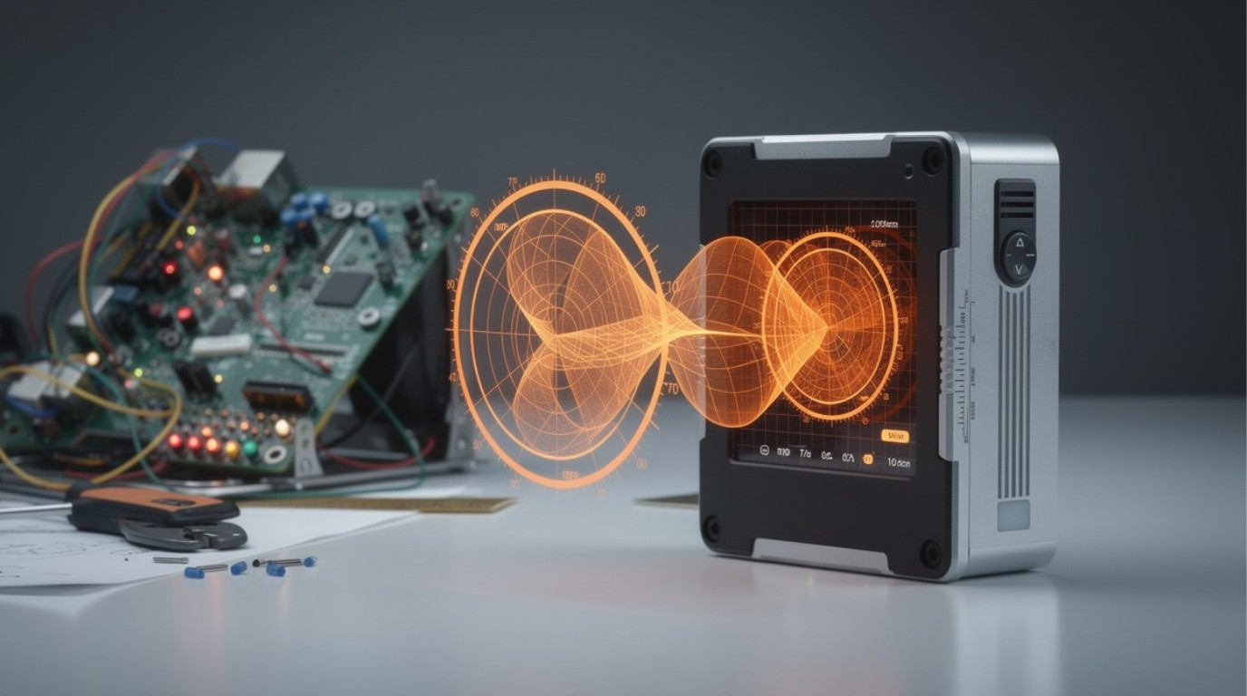
BLE Channel Sounding demonstrations are easy to get working.
The nRF54H20 sample application compiles, the EFR32xG24 dev kit ships as an initiator-reflector pair, and within a day a team can display a distance readout in a serial terminal. The readout will look compelling (sub-metre, responsive, and consistent) right up until the hardware moves into the environment it is actually intended for.
Production Channel Sounding fails for reasons that do not appear in a clean-room demonstration. Phase wrapping that the demo SDK masks. Antenna coupling that corrupts phase measurements on a real PCB layout. Multi-path reflections from warehouse shelving that report a tag as close when it is around a corner. Authentication gaps that a relay attacker can exploit. These are not edge cases: they are the difference between a BLE ranging prototype and a certified product shipping at volume.
This article covers seven implementation decisions where teams consistently discover these gaps. Each decision has a common pattern of what gets skipped in a demo and what a production-grade implementation requires. The Bluetooth SIG’s BLE 6 Channel Sounding specification defines what the protocol must do; these seven decisions describe what the implementation must handle.
Decision 1: PBR or IBT and the accuracy consequences of choosing wrong
The CS specification defines two ranging methods. Phase-Based Ranging (PBR) measures the phase of received radio tones across multiple frequency channels. Initiator-Based Timing (IBT, also called Round-Trip Time or RTT) measures the elapsed time for a CS SYNC packet to travel from initiator to reflector and back. Both are valid, standardised CS methods. They are not equivalent in accuracy or in implementation complexity.
IBT accuracy in practice lands between 0.5 and 1 metre under line-of-sight conditions. It requires no phase measurement, no multi-tone processing, and no integer ambiguity resolution. This is why it appears in most demo implementations: it is achievable with SDK defaults and requires minimal RF tuning. Many CS demonstrations presented at trade shows and in vendor application notes use IBT or a hybrid heavily weighted toward IBT.
PBR, when implemented with proper multi-tone processing, achieves sub-30 cm accuracy under line-of-sight conditions on current chipsets. It requires phase measurement across multiple tones, integer ambiguity resolution, and an antenna layout that preserves phase integrity. It is meaningfully harder to ship than IBT.
The choice matters because many BLE Channel Sounding applications specify sub-metre accuracy as a requirement. A digital key that unlocks a car at 30 cm separation but not at 1.2 metres needs PBR. An industrial safety zone boundary at 50 cm needs PBR. A warehouse asset proximity alert at 2 metres may be fine with IBT. The mistake is not choosing IBT: it is choosing IBT while claiming PBR-class accuracy, or beginning development with IBT and discovering late in the project that the target accuracy requires switching to PBR and revisiting antenna design.
The correct sequencing is to establish the accuracy requirement first, confirm which ranging method meets it, and design the hardware and firmware from that point. Switching from IBT to PBR after PCB layout is finalised is a re-spin.
Decision 2: Integer ambiguity resolution, the step most CS implementations skip
Phase-Based Ranging works by measuring how much a radio signal’s phase has rotated during transit. The problem is that phase is periodic: it completes a full 360° rotation every wavelength. At 2.4 GHz, one wavelength is approximately 12.5 cm. A device at 12.5 cm produces the same single-tone phase reading as a device at 25 cm, 37.5 cm, or any multiple of 12.5 cm. A single-tone PBR implementation cannot distinguish these distances and therefore cannot report accurate absolute range beyond a few centimetres.
Integer ambiguity resolution is the process of determining which cycle of phase rotation the measured phase belongs to. The solution is multi-tone measurement: by transmitting and measuring phase across many different frequency channels, the rate of phase change across frequencies encodes the absolute distance. This is essentially the same technique used in radar and sonar ranging and is central to why the CS specification uses up to 72 radio channels rather than a single frequency.
The accuracy figure that Silicon Labs documents PBR accuracy of ±0.3 m within 5 metres for the EFR32xG24 assumes a multi-tone implementation with working integer ambiguity resolution. Without it, PBR measurements are only meaningful within the first half-wavelength, roughly 6 cm, and degrade in a non-linear and often misleading way beyond that.
Implementing integer ambiguity resolution requires choosing an algorithm. Common approaches include least-squares phase unwrapping, MUSIC (Multiple Signal Classification), and variants of SAGE. Each trades processing cost against accuracy and robustness to noise. Tone count matters too: more tones across a wider frequency span improve ambiguity resolution but extend the CS procedure duration, which increases power consumption and reduces the ranging update rate.
Teams building a CS implementation should request explicit information from their firmware partner about which algorithm is used, at what tone count, and what the measured accuracy is at distances of 1, 2, 3, and 5 metres, not only at distances under 50 cm where single-tone approaches can appear accurate.
Decision 3: Antenna design and RF front-end, where software-only teams hit a ceiling
PBR measures phase. Phase measurement accuracy depends not only on the algorithm but on the quality of the received signal’s phase information as it arrives at the chip’s RF front-end. Several hardware factors directly corrupt phase measurements and cannot be corrected in firmware after the fact.
Antenna return loss (S11). Poor impedance matching at the antenna results in signal reflection at the antenna port, which alters the phase of both transmitted and received signals. An antenna tuned to 50 Ω with proper return loss below −10 dB provides clean phase information; a poorly matched antenna introduces systematic phase errors across all tones.
TX and RX path isolation. CS procedures alternate between transmission and reception within very short time windows. If the transmit signal leaks into the receive path, due to insufficient isolation on the PCB layout, and creates in-band interference that appears as a phase offset. This is particularly problematic when the CS initiator and reflector are on the same board or in close physical proximity, as in a two-antenna reference design.
PCB ground plane and component placement. Parasitic capacitance between the antenna feed trace and nearby copper affects the antenna’s resonant frequency and radiation pattern. CS firmware cannot correct for a mistuned antenna any more than a calibration algorithm can compensate for a physically damaged ADC.
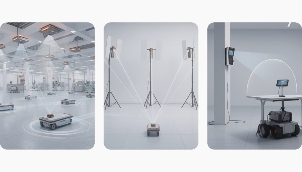
Antenna diversity for multi-path mitigation. The CS specification supports up to four antenna paths between initiator and reflector, using antenna switching during the CS procedure. Implementing multi-antenna CS requires physical antenna switch circuitry, correctly timed switch control signals, and calibrated path-specific phase offsets. A single-antenna CS design performs acceptably in line-of-sight; multi-antenna diversity is what maintains accuracy when the direct path is partially obstructed.
The practical implication: a software-only development team that inherits an existing BLE PCB layout and adds CS firmware will encounter antenna-related phase errors that firmware tuning cannot fully correct. CS antenna design requires RF hardware engineering alongside firmware development. Teams that discover this mid-project typically face a PCB re-spin or accept lower-than-specified accuracy.
Decision 4: CS procedure parameters, why SDK defaults are not production settings
The CS specification exposes a set of configurable parameters that control how each ranging procedure is executed. Chipset SDK defaults are chosen to work reliably in a clean, unobstructed lab environment. Production environments are not lab environments, and the consequences of running factory-default CS parameters in a congested or obstructed space range from reduced accuracy to intermittent ranging failures.
Tone count and step count. Each CS procedure consists of a series of steps, each of which captures one tone measurement (for PBR) or one timing measurement (for IBT). More steps per procedure produce more data points for the ambiguity resolution algorithm, improving accuracy and reducing the influence of individual corrupted measurements. Fewer steps reduce procedure duration and power consumption. The right balance depends on the target environment’s noise floor and the acceptable ranging update rate.
T_IP (inter-tone interval). This is the time between consecutive tone measurements within a PBR step. Too short and the radio front-end may not fully settle between transmissions, introducing phase measurement noise. Too long increases procedure duration without accuracy benefit. Chip vendor documentation specifies minimum T_IP values; real PCB layouts may need longer intervals to account for antenna settling.
T_FCS (frequency calibration step interval). CS procedures include frequency calibration steps that compensate for frequency offset between the initiator’s and reflector’s clocks. The frequency calibration interval determines how often this correction is applied within a procedure. In environments with strong temperature gradients or where devices use low-quality oscillators, more frequent calibration reduces accumulated frequency error between ranging tones.
CS channel map. The CS specification allows selection of which of the 72 available channels to use for a procedure. In a 2.4 GHz environment crowded with Wi-Fi, microwave interference, or other BLE traffic, excluding known-congested channels from the CS channel map reduces the proportion of corrupted tone measurements. This requires RF environment characterisation before deployment, not after.
Parameter tuning requires iterative measurement: run ranging at target distances in the deployment environment, record accuracy and consistency across multiple procedures, vary one parameter at a time, and repeat. Teams that skip this step and ship with SDK defaults typically discover in field validation that their accuracy figures do not replicate what the bench test showed.
Decision 5: Security architecture, authentication levels and relay attack defence
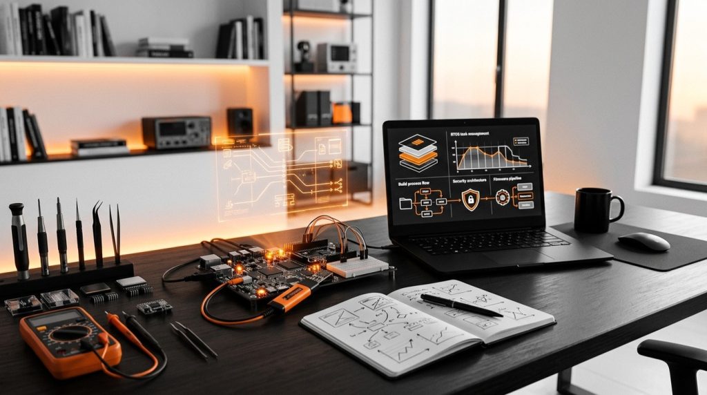
CS provides centimetre-to-sub-metre ranging. For access control applications (digital car keys, smart door locks, industrial zone enforcement), this precision is what makes CS valuable over RSSI. It is also what makes the security architecture critical. A proximity system that can be defeated by a relay attack is not meaningfully more secure than RSSI proximity regardless of its ranging accuracy.
The CS specification defines four authentication levels:
Level 1: Distance measurement only, with no authentication. A CS procedure runs over a standard Bluetooth connection with no additional security binding. Suitable for non-security-critical ranging (pet tracking, approximate zone detection) where the ranging result does not gate access.
Level 2: CS procedures run over an encrypted Bluetooth connection. The ranging result is protected from eavesdropping, but the procedure itself is not authenticated: an attacker who controls one end of the connection can still influence the CS outcome.
Level 3: CS procedure randomisation is seeded using a Distributed Random Bit Generator (DRBG) derived from a shared secret established during pairing. This makes CS procedure parameters unpredictable to an attacker who does not possess the shared secret. Relay attacks become significantly harder because the relay must faithfully forward the full CS procedure exchange, including timing.
Level 4: Full FIPS-compliant DRBG seeding with verified key exchange, providing the strongest cryptographic binding between the shared secret and CS procedure randomisation.
Access control applications should implement level 3 or 4. Shipping a digital key product with level 1 or 2 security while advertising CS-class ranging accuracy is a security specification that does not match its implementation.
Relay attacks on CS are different from relay attacks on RSSI-based proximity. RSSI relay attacks work by amplifying the signal strength; CS relay attacks attempt to relay the timing-sensitive CS procedure itself across a relay device. RTT-based CS (IBT) is inherently more resistant to relay because round-trip time cannot be shortened by a relay, since the relay adds latency. PBR-based CS with authentication level 3 or 4 adds the DRBG seeding layer that makes CS procedure replay attacks non-viable.
Nordic’s nRF54H20 integrates hardware cryptographic acceleration targeted at PSA Certified Level 3 security, providing the hardware root-of-trust that CS authentication levels 3 and 4 build on. For a production access control design, hardware security subsystem capability is as important as ranging accuracy in chipset selection.
needCode’s Trusted Proximity protocol implements both PBR ranging and cryptographic authentication in a single CS procedure, binding physical proximity to device identity. This means a CS access event includes a simultaneous distance measurement and device authentication, rather than running authentication and ranging as separate sequential steps that could be decoupled by an attacker.
Decision 6: NLOS detection and mitigation, the production failure mode nobody demonstrates
Non-line-of-sight (NLOS) conditions are the largest single source of divergence between demonstrated CS accuracy and deployed CS accuracy. Lab demonstrations almost universally use open bench or open floor space. Production environments have walls, shelving, vehicles, and people, all of which cause multipath propagation that directly corrupts PBR phase measurements.
The failure mode is specific. In line-of-sight, the dominant signal path is the direct path between initiator and reflector. PBR phase measurements are dominated by this direct signal, and the range estimate is accurate. In NLOS, reflected signals from nearby surfaces arrive at the reflector at comparable amplitude and only slightly later than the direct path. These reflections mix with the direct-path signal, shifting the apparent phase and producing a range estimate shorter or longer than the true distance. When a strong reflection arrives from a surface between the devices, the reported distance can be significantly shorter than the true distance, which is particularly dangerous in a safety application that gates an action on a device being “outside a zone.”
NLOS detection relies on the statistical properties of CS measurements across multiple tones and multiple procedures:
Phase variance across tones. In line-of-sight conditions, PBR phase measurements across tones change smoothly with frequency in a pattern consistent with a single delay. NLOS causes irregular phase variation across tones as multiple delayed paths add constructively and destructively at different frequencies. High inter-tone phase variance is a reliable NLOS indicator.
Confidence interval monitoring. Running multiple CS procedures and computing the standard deviation of range estimates provides a real-time NLOS confidence metric. A standard deviation much higher than the expected measurement noise indicates multipath corruption.
Multi-antenna diversity. When CS measurements across two or more antenna paths diverge significantly, this indicates that the antenna paths are receiving different multipath contributions, a strong NLOS indicator. Single-antenna designs have no access to this diagnostic.
Fallback behaviour. When NLOS is detected, a production CS system should have a defined response: widen the proximity zone boundary, discard the measurement and wait for the next procedure, switch from PBR to IBT (which is less accurate but more robust to moderate NLOS), or hold the last known good estimate. The worst response is no response: continuing to act on a range estimate flagged as potentially corrupted.
A CS implementation that lacks NLOS handling will appear to work in a demo and produce safety-relevant failures in a real environment. NLOS testing requires a representative physical environment, such as a real room, warehouse, or outdoor space with the obstacles and surfaces present in the deployment, not a bench.
Decision 7: Validation framework, from lab table to certified interop
CS validation is a multi-stage process. Teams that treat any single stage as sufficient for production sign-off typically discover failures in a later stage that require returning to earlier work.
Reference distance fixture. Ranging accuracy should be validated against a mechanical fixture (rails, foam block, or rigid jig) that holds initiator and reflector at known distances: 0.5 m, 1 m, 2 m, 3 m, 5 m, and 10 m as a minimum set. At each distance, run a statistically meaningful number of CS procedures (at least 100) and record the mean and standard deviation of range estimates. This produces the accuracy characterisation that should appear in any product specification or marketing claim. Some teams supplement fixture testing with a dedicated channel sounder, which provides calibrated RF path measurements independent of the CS implementation under test.
Environment replication. Free-space accuracy on a reference fixture is a necessary first step, not a final result. Repeat the fixture measurement inside a representative space, the target deployment environment or a physical analog. Record how accuracy and standard deviation change. If your product targets warehouse deployment and your validation was done in an open office, your accuracy data may not represent field performance.
Side-by-side RSSI baseline. For any CS deployment that positions itself against RSSI proximity, run parallel RSSI ranging at the same test distances and record both results. This makes the accuracy improvement concrete and provides the comparison data needed to justify BOM cost increase versus an RSSI-only design.
Bluetooth SIG CS qualification. CS adds test cases to the standard Bluetooth qualification program. Products using Channel Sounding must qualify these CS-specific test cases through the Bluetooth SIG’s Qualification Process. Qualification is not optional if the product will carry the Bluetooth logo; skipping qualification creates market access risk in major markets.
Interoperability with phone CS hardware. Android’s Channel Sounding API, available from Android 15, defines the host-side procedure parameters that CS-capable Android phones expose. For phone-as-key or consumer-facing CS applications, validation against actual Android CS-capable hardware, not only Android CS software API, is required. The list of Android devices with CS-capable chipsets is narrower than the list of devices running Android 15. Validate against target phone models, not OS version alone.
Regression in firmware updates. CS accuracy is sensitive to firmware changes that affect radio timing, interrupt latency, or tone scheduling. A firmware update that improves one feature can silently degrade CS accuracy. Production CS systems should include automated ranging accuracy regression tests that run against the reference fixture before each firmware release.

Production readiness quick reference
| Decision | Common demo shortcut | Production-grade requirement | Quick self-check |
|---|---|---|---|
| PBR vs IBT | IBT only (simpler to demo) | PBR or hybrid with documented accuracy target | Do you have PBR accuracy data at 1 m, 3 m, and 5 m? |
| Integer ambiguity | Single-tone or SDK default | Multi-tone processing with validated resolve rate | Can you show consistent accuracy beyond 25 cm without wrapping errors? |
| Antenna design | Off-the-shelf antenna, unchanged PCB | RF-characterised layout, measured S11, TX/RX isolation | Have you measured S11 and TX/RX isolation on your actual PCB? |
| CS procedure parameters | SDK defaults | Environment-tuned tone count, T_IP, T_FCS, channel map | Have you run a parameter sweep in your target deployment environment? |
| Security architecture | No authentication or level 1–2 | CS auth level 3–4, relay attack test | Have you tested a relay attack scenario against your implementation? |
| NLOS detection | No NLOS handling | Phase variance monitoring, fallback behaviour defined | Does your firmware flag NLOS conditions and define a response? |
| Validation framework | Bench accuracy only | Fixture data + environment data + SIG qualification + interop | Have you validated accuracy in the target physical environment with actual endpoint hardware? |
needCode builds and supports BLE Channel Sounding systems, from PBR firmware and integer ambiguity resolution to CS security architecture and Bluetooth SIG qualification. If you are building a production BLE ranging product and want an engineering team that has worked at the Bluetooth SIG specification level, we are happy to talk. Book a free discovery call or get in touch.
CS demos typically run in open, unobstructed spaces with reference hardware antennas and factory-default SDK parameters. Production accuracy degrades for several reasons: NLOS conditions from walls and obstacles corrupt PBR phase measurements; real PCB antenna layouts introduce phase errors that a clean demo board avoids; and SDK parameter defaults are calibrated for lab conditions, not congested RF environments. The accuracy gap between demo and deployment is predictable and addressable — but only if each factor is specifically handled.
PBR measures the phase shift of radio signals across multiple frequency tones to estimate distance. Because phase is periodic — repeating every wavelength, approximately 12.5 cm at 2.4 GHz — a single-tone measurement cannot distinguish 12.5 cm from 25 cm or 37.5 cm. Multi-tone processing across many channels resolves this ambiguity and recovers the absolute distance. Without integer ambiguity resolution, a PBR implementation only reports accurate distances within the first few centimetres of separation.
Access control applications should implement authentication level 3 at minimum, and level 4 where FIPS-compliant security is required. Levels 1 and 2 do not provide adequate relay attack mitigation for applications where the ranging result controls physical access. CS authentication levels 3 and 4 use DRBG seeding from a shared secret to make CS procedure parameters unpredictable to an attacker.
In NLOS conditions, reflected signals from obstacles arrive at the reflector with comparable amplitude to the direct signal. These reflections mix with the direct-path signal, shifting the apparent phase and producing a range estimate that differs — often significantly — from the true distance. The error is systematic and direction-dependent, not random noise. NLOS detection using phase variance across tones and multi-antenna diversity can identify corrupted measurements; a defined fallback behaviour is required when NLOS is detected.
Yes. Products using Channel Sounding that carry the Bluetooth logo must complete the Bluetooth SIG’s Qualification Process, which includes CS-specific test cases added in Bluetooth Core Specification 6.0. Skipping qualification creates market access risk in regions that require Bluetooth certification for wireless device approval.
needCode’s PBR engine implements multi-tone phase measurement with proprietary integer ambiguity resolution, validated across multiple distance ranges. The engine is integrated into their Trusted Proximity protocol, which combines ranging and cryptographic device authentication in a single CS procedure. This approach was developed on Nordic nRF54H20 and nRF5340 hardware, with the team drawing on direct Bluetooth SIG specification experience from BLE Mesh development.