
The EU Cyber Resilience Act enters enforcement in 2027.
ETSI EN 303 645 is already shaping European procurement for consumer IoT. NIST IR 8259 establishes the baseline for U.S. federal IoT procurement. Each of these frameworks imposes mandatory security requirements on products with digital elements, and each of them places the burden of demonstrating compliance on the manufacturer, not on their silicon vendor.
What this means for an embedded SDK team is concrete. Customers shipping into regulated markets will start asking specific questions during platform evaluation: which PSA Certified level does your SDK target, what TF-M isolation level is configured by default, what secure boot chain do you ship, what OTA pipeline do you provide, and which exact software version corresponds to your certification listings. An SDK that can answer these questions cleanly is a product. An SDK that cannot is a liability that customers route around.
The harder truth is that the architectural decisions required to answer them cannot be retrofitted at low cost. Security as an additive feature — bolted on after the HAL and RTOS design are complete — does not work, because the secure-versus-non-secure world split, the secure boot chain, the key storage model, and the OTA authentication pipeline all interact with the memory map and the peripheral access policy. Changing those after peripheral drivers are written requires re-validating every driver that touches a memory-mapped register, because the SAU and IDAU configuration determines which addresses are accessible from which world.
This post walks through the four pieces an embedded security framework has to put in place — PSA as the umbrella, TF-M as the implementation, MCUboot for secure boot, and an OTA pipeline that satisfies four non-negotiable properties — and what it costs to assemble them after the fact instead of designing them in from silicon generation one.
PSA: the umbrella the rest of the stack hangs from
Arm’s Platform Security Architecture is an architecture-agnostic framework for building secure IoT products. It defines a threat model, a security analysis methodology, and a set of security functions: a Root of Trust, secure boot, cryptographic services, and remote attestation. PSA Certified is the associated certification scheme, and it has three levels that progressively raise the security bar at the cost of additional engineering and lab investment.
PSA Certified Level 1 is questionnaire-based. The vendor submits a threat model and supporting documentation, and the certification body reviews it. There is no mandatory hardware security requirement at Level 1. The TF-M isolation level can be 1, 2, or 3. This is the appropriate target for basic IoT devices that need a defensible compliance position without a major hardware investment.
PSA Certified Level 2 is lab-evaluated. It requires hardware isolation, typically TrustZone-M or an equivalent dual-core design. A minimum TF-M isolation level of 2 is required, with the exception of an ARoT-less profile available since late 2022 that allows constrained devices to certify at Level 2 with TF-M isolation Level 1. This is the level most connected consumer and industrial IoT products will target for CRA compliance.
PSA Certified Level 3 adds resistance to hardware attacks, including physical penetration testing and side-channel attack mitigation. TF-M isolation Level 3 is mandatory. This is the level required for high-value assets: payment terminals, medical devices, and infrastructure equipment where the device itself is the attack surface.
The choice of target level is not purely a technical decision. It is a market-positioning decision that has to be made early, because the silicon and SDK architecture required to support Level 2 or Level 3 has to be present from the first generation. An SDK targeting Level 1 customers can still serve a Level 2 customer who provides their own additional measures, but an SDK whose architecture cannot support Level 2 — because it has no TrustZone story, no isolated key storage, no signed boot chain — cannot retrofit those properties without a silicon revision.

TF-M: the open-source reference implementation
Trusted Firmware-M is the open-source reference implementation of PSA for Armv8-M devices (Cortex-M23, M33, M55, M85) and compatible dual-core platforms. It implements the Secure Processing Environment that runs in the TrustZone Secure world, isolated from the Non-Secure Processing Environment where the application RTOS and user code execute.
The services TF-M exposes through PSA Functional APIs are the building blocks the rest of the security framework rests on:
PSA Crypto provides the cryptographic primitives: AES-GCM, ChaCha20-Poly1305, ECDSA P-256 and P-384, RSA-2048 and 4096, SHA-2 and SHA-3, HKDF, PBKDF2. The cryptographic backend is mbedTLS, with the PSA Crypto API as the stable interface that application code targets. Application code never links against mbedTLS directly; it goes through PSA Crypto, which means the underlying implementation can be replaced without breaking applications.
Internal Trusted Storage is a secure key-value store backed by on-chip flash with hardware-enforced access protection. Private keys stored in ITS are never exposed to the Non-Secure world. An application that needs to sign a message asks ITS to perform the signing operation; the key never leaves the secure side.
Protected Storage is encrypted and authenticated persistent storage using AES-256-GCM AEAD, suitable for certificates, provisioning credentials, and configuration secrets that need to survive reboots and resist offline attacks on the flash contents.
Initial Attestation generates a COSE/CBOR-signed token describing device identity and security state, enabling remote attestation in zero-trust deployment architectures. The token is what proves to a backend that the device is what it claims to be and is in the configuration it claims to be in.
Firmware Update Service verifies incoming firmware images cryptographically before handing control to the bootloader for installation. This is where TF-M and the OTA pipeline meet.
TF-M’s three isolation levels track the PSA Certified levels, and the choice has direct implications for performance and image size. Isolation Level 1 maintains only the SPE-versus-NSPE boundary; the PSA Root-of-Trust and Application Root-of-Trust share the same privilege level within the secure world. Isolation Level 2 adds an MPU boundary between the PRoT and ARoT, so ARoT secure partitions cannot access PRoT memory directly. Isolation Level 3 isolates each secure partition in its own MPU region, providing the maximum boundary granularity at the highest performance and image-size cost.
The Secure Partition Manager is the TF-M kernel. It manages secure partition lifecycle and mediates inter-partition communication through two mechanisms: an IPC call (message-passing through a mailbox) and a Secure Function call (a direct call with lower overhead). Which mechanism a partition uses is a design choice with implications for both isolation and performance, and the choice has to be made consistently across the SDK’s secure services.
The secure boot chain: from reset vector to application
A secure boot chain establishes a cryptographically verified path from the hardware Root of Trust to application code. Every stage verifies the integrity and authenticity of the next stage before transferring control. The chain has to be designed in advance, because retrofitting it requires re-laying-out the memory map and re-signing every existing image.
A typical modern chain for a TrustZone-capable Cortex-M33 device looks like this:
Reset Vector
|
v
[BL2 – Immutable Bootloader (Secure world)]
– Stored in ROM or OTP-locked flash region
– Verifies BL33 (TF-M SPE) image signature: ECDSA P-256
– Verifies Non-Secure application image signature
– Enforces anti-rollback via monotonic counter in OTP
|
v
[BL33 – TF-M Secure Processing Environment]
– Configures TrustZone SAU/IDAU memory partitions
– Initialises Secure Partitions via SPM
– Transfers control to Non-Secure entry point
|
v
[NS Application (RTOS + User Code)]
– Accesses crypto/storage via PSA API -> TF-M SVC gate
– Cannot access Secure world memory directly
The properties that matter at each stage are not negotiable. BL2 must be immutable — stored in ROM, or in an OTP-locked flash region — because if BL2 can be modified, the entire chain of trust collapses. BL2 must verify image signatures using a public key whose private counterpart is held by the device manufacturer, not by the silicon vendor and not by an intermediate party. Anti-rollback must be enforced through a monotonic counter in OTP, so that an attacker cannot downgrade the device to an older, vulnerable image even if they have a validly signed copy of it.
MCUboot is the standard open-source bootloader used in this chain. It supports two image slots — primary and secondary — and three upgrade modes. Overwrite-only is the smallest in flash overhead but provides no rollback. Swap is copy-then-overwrite with full rollback capability. Direct-XIP executes in place from the secondary slot without copying, which is useful for external flash but does not provide the same atomic rollback guarantees as swap.
Swap mode is strongly preferred for production because it enables atomic rollback: if the new image fails to confirm itself within a configurable timeout, the bootloader automatically restores the previous image on the next reset. This single property eliminates an entire class of failure mode in which a bad update bricks the device, and it is the property that customers rely on when they are deciding whether to enable automatic OTA updates in production fleets.
The OTA pipeline: four properties, no shortcuts
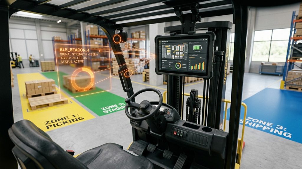
A production OTA pipeline must satisfy four properties simultaneously. Atomicity, authentication, rollback safety, and resumeability. None of them is optional, and each of them rules out specific implementation shortcuts that look attractive in early-stage development.
The pipeline for a typical IoT MCU with internal flash plus an external QSPI flash for staging proceeds in four phases.
Image fetching. The device downloads the update image — compressed and signed — to the secondary slot in internal flash, or to a staging region in external flash. The download must be resumable via byte-range requests, because connections drop, and an OTA pipeline that has to restart from zero on every connection failure is unworkable on real-world cellular and Wi-Fi links. If the image is fetched through MQTT, CoAP, or HTTPS, that transport has to support byte-range fetching.
Cryptographic verification. The bootloader verifies the image signature using the public key provisioned into the device at manufacturing. The signature must cover the entire image binary plus a structured header containing version, size, flags, and hash. Any signature verification failure aborts the update and triggers an alert. The signing key never lives on the device; it lives in the manufacturer’s signing infrastructure, and the device only ever sees the public counterpart.
Integrity check. A hash checksum of the image payload — SHA-256 or SHA-384 — is verified independently of the signature. This catches transport corruption that would not necessarily produce a signature failure on its own.
Swap and commit. The bootloader atomically swaps the primary and secondary slots. The new image runs and has a configurable window to confirm itself by calling the appropriate MCUboot API. If it does not confirm within that window, the bootloader reverts to the prior image on the next reset. This is what makes OTA recoverable from a bad update, including a bad update that crashes immediately on first boot.
An SDK that integrates OTA as a first-class subsystem, rather than as an application-layer addition, provides significant differentiation. It enables customers to demonstrate compliance with the CRA’s requirement for ongoing vulnerability patching over the device lifetime, and it reduces the integration risk for cloud-connected device fleets where a bad update across a million devices is a business-ending event.
What “security as architecture” actually means
Security cannot be bolted on after the HAL and RTOS design are complete. The reasons are not philosophical, they are mechanical.
The secure-versus-non-secure world split affects which addresses peripheral drivers can use. Adding a TrustZone boundary after drivers are written means re-validating every driver that touches memory-mapped registers, because the SAU and IDAU configuration determines accessibility from each world. Drivers that worked in a flat-memory-map development environment may fault, silently misbehave, or read back unexpected values once the security partition is in place.
The key storage model affects how cryptographic operations are exposed. An application written against a flat crypto API that calls mbedTLS directly cannot be ported to a PSA-Crypto-based key storage model without rewriting every call site. Applications that target PSA Crypto from the start are portable across both models.
The OTA authentication pipeline affects how the application is laid out in flash. Applications written without an OTA-aware linker layout cannot be retrofitted into a dual-slot, signed-image format without changing the build configuration, the linker scripts, and the post-processing steps. Customers who shipped a generation of products without OTA cannot easily add it later, which is exactly the situation the CRA is designed to prevent.
This is why “security as architecture” is the framing that matters. The decisions to make are not whether to enable cryptography or whether to sign images. They are whether the memory map has a TrustZone partition, whether the key storage goes through PSA Crypto from the first release, whether the boot chain has a defined root of trust, and whether the application is laid out in flash to support a dual-slot OTA model. These decisions have to be made before the first peripheral driver is written, because changing them afterwards costs more than building them in.

The deadline doesn’t move
The 2027 CRA enforcement date is not aspirational. It is a fixed regulatory milestone that customers shipping into the European market will plan their procurement against, starting in 2026 if they have not started already. Silicon vendors whose SDKs target PSA Certified Level 2 by default, with TF-M integrated, MCUboot ship-ready, and OTA pipelines that satisfy the four properties out of the box, will be on the shortlist for those design-wins. Vendors whose SDKs are still positioning security as a customer-integration exercise will be answering harder questions in those evaluations than they want to.
The architectural patterns are well-understood. The reference implementations exist, are open source, and serve hundreds of millions of devices today. The cost of adopting them is real but bounded. The cost of not adopting them is unbounded, because it shows up not as a clean line item but as a slow erosion of the design-win pipeline in regulated markets, on a timeline that does not allow for course-correction once it has started.
The 2027 CRA deadline is fixed. Your security architecture has to be in place before your next silicon generation.
needCode designs embedded SDKs with PSA Certified targeting, TF-M integration, and OTA pipelines built in from day one — not retrofitted after the HAL is written. If you’re evaluating your security architecture ahead of CRA enforcement, let’s talk.
Book a free discovery call or get in touch
Further reading
- Anatomy of a Production OTA Pipeline — the OTA subsystem this article’s security framework depends on, covered in full detail including fault injection and rollback safety
- Firmware Security — how needCode implements PSA Certified targeting, secure boot, and key storage across connected product deployments
- FreeRTOS / Zephyr OS — the RTOS layer that runs in the Non-Secure Processing Environment alongside TF-M’s Secure Processing Environment
- Opaque Handles, Vtables, and Device Trees — the HAL design patterns that have to be in place before the TrustZone boundary is introduced